– 24 –
Calibration Instructions
for the Inductive Sensors
Note: Calibration of the inductive sensors must
begin with the LF surface element and proceed in
a
clockwise direction around the cooktop. All of
the sensors
must be calibrated to complete the
calibration procedure.
• Calibration of the inductive sensors
must begin
within 15 minutes of applying power to the
cooktop.
1. Clear everything from the top of the glass.
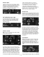
2. Lock the control by pressing the control LOCK
key for 3 seconds. The control LOCK LED will
turn ON.
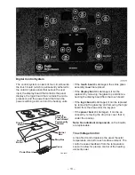
3. Enter tech mode by pressing the TIMER
ON/OFF, LF (+), and LR (+) keys at the same
time. The TIMER window will flash the words
TECH MODE.
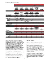
4. Begin the calibration procedure by pressing the
TIMER ON/OFF, LF (+), and RF (+) keys at
the same time. The TIMER window will flash
CAL and the LF surface element power win-
dow will flash the U symbol.
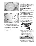
6. Disconnect the power connector in the burner
box.
Caution: To avoid delivering an electric shock to
the new power board, place your hand on the
burner box for
at least 2 seconds before reaching
for the new power board.
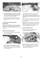
7. Remove the new power board from the anti-
static bag and reconnect the 26-pin wire har-
ness, the main power connector, and the burner
box power connector to their original positions.
8. Examine the inside of the cooktop (heaters,
sensors, wires, and thermal wall) for anything
that does not look normal.
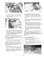
3. Remove 5 screws and the ground screw from
the drop box cover and lower the cover.
26-Pin Cable
26-Pin Cable
26-Pin Cable
Main Power Connector
Main Power Connector
Main Power Connector
GEA00826
4. Disconnect the main power connector in the
drop box.
5. Disconnect the 26-pin ribbon cable from the
power board by pressing down on the latching
tabs of the header.
Power
Power
Connector
Connector
Power
Connector
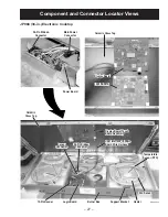
9. Prop the glass onto the back of the cooktop.
Using one hand to lower the glass, use the
other hand to connect the wire harness from
the user interface to the 10-pin header on the
logic board.
10. Lower the glass onto the burner box, being
sure not to pinch any wires between the frame
and the burner box.
11. Apply power to the cooktop. Once the cooktop
appears to be in working order, remove power
from the cooktop and insert all the screws to
secure the frame to the burner box.
Summary of Contents for Profile JP938
Page 19: ...17 Fault Code Behavior Table...
Page 33: ...31 Notes...
Page 34: ...32 Parts List...
Page 36: ...34...
Page 38: ......
Page 39: ......

