background image

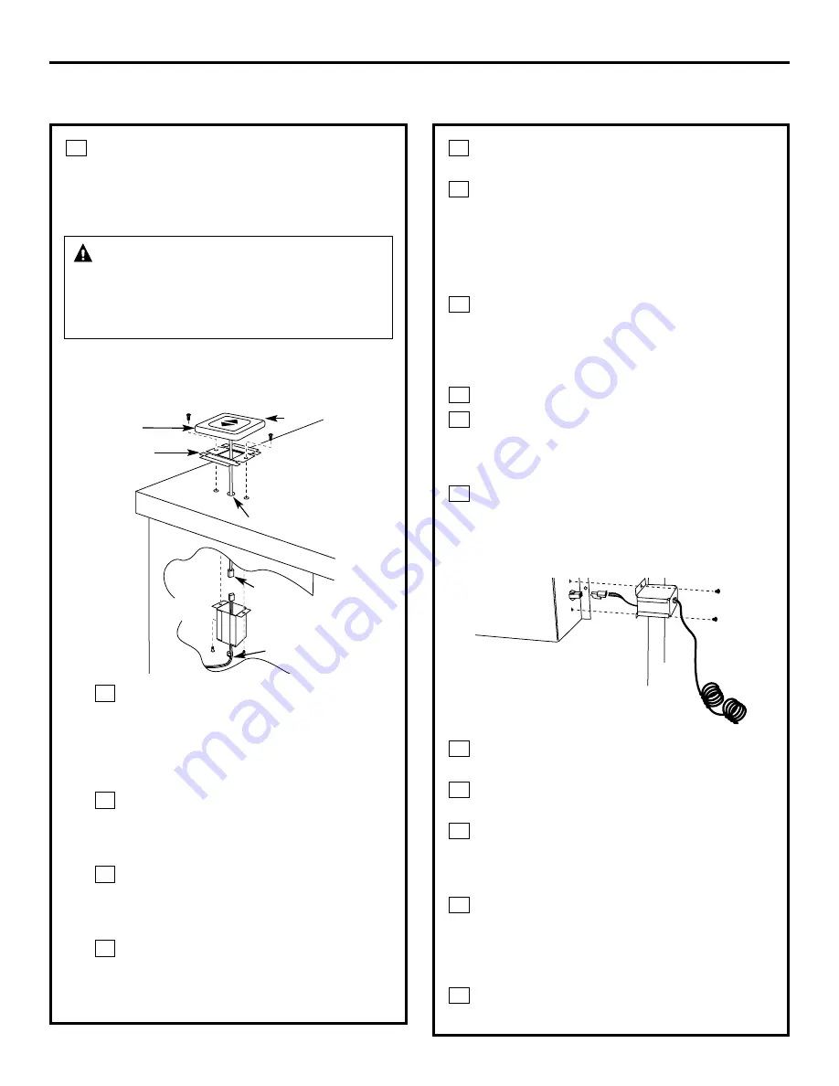
INSTALL THE RAISE/LOWER

SWITCH

NOTE: Step 3 is for 36

models only. 

Skip this step if installing a 30

model.

NOTE: 

Determine the location for the

Raise/Lower switch. The wiring lead is

68

long.

Drill a 3/8

hole into the desired

location. Use the mounting bracket

as a template to locate the hole

accurately. Check for interference

between the switch cover, adjacent

objects and cooktop/vent overlaps.
If switch is mounted into a tile

surface, drill the hole between tiles.

Use locally approved caulking to

cover any gaps.
Center the mounting bracket over the

hole and mark pilot holes. Remove

and drill holes according to type of

countertop.
Mount the metal switch bracket 

with screws (not provided). Choose

screws for your type of countertop 

or use locally approved adhesive.

D

C

B

A

3

16

Installation Instructions

INSTALLING THE DOWNDRAFT VENT SYSTEM

WARNING

Disconnect electrical

power from the unit before beginning switch

installation. Failure to do so could result in

personal injury or damage to the electrical

controls.

Remove protective film from the top of

the switch trim.
Peel film from the adhesive strips on the

back of the switch trim. Thread the wire

lead through the mounting bracket and

countertop. Press trim over the mounting

bracket to set the adhesive.

Connect Raise/Lower Wire Lead to Wire Box

Thread wire end with the connector

through the hole on the end of a wire

box. Pull approximately 3

additional

wire length beyond the open end of 

the box.
Connect the mating wire connectors.
Install the wire box onto the bottom of

the countertop or directly behind the

switch. Use screws or adhesive

appropriate for the type of countertop.
Place plastic strain relief over the wire,

just outside of the hole at the end of the

wire box. Do not pinch or twist the wire.

Snap the strain relief closed and press

into the hole.

Connect Wire Lead to Control Box

Thread the long 68

wire lead through

the end of the other wire box.
Push wire leads into the white connector

provided.
Push wire connector into the mating

connector on the control box. Install the

wire box onto the end of the control box

with screws provided.
Place plastic strain relief over the wire,

just outside of the hole at the end in the

wire box. Do not pinch or twist the wire.

Snap the strain relief closed and press

into the hole.
Coil the excess wire and position away

from moving parts and cabinet contents.

E

D

C

B

A

D

C

B

A

F

E

Trim

Mounting

bracket

3/8

Hole

Raise/Lower

switch

2 Pin

connector

Strain relief

Pull 3

length

out of

box

Control box

Summary of Contents for Profile JVB67HBB

Page 1: ...for local inspector s use IMPORTANT Observe all governing codes and ordinances Note to Installer Be sure to leave these instructions with the Consumer Note to Consumer Keep these instructions for fut...

Page 2: ...or ceiling do not damage electrical wiring and other hidden utilities WARNING To reduce the risk of fire use only metal ductwork C B A IMPORTANT These vents are recommended for island installations Ag...

Page 3: ...placing cabinetry directly above the cooking surface when possible If cabinetry is used above the cooking surface Installation must conform with local codes Use cabinets no more than 13 deep Maintain...

Page 4: ...cabinets Maintain cutout clearances to front edge as specified In an island or peninsula the countertop can be extra deep to provide seating opposite of the cooktop Adding base cabinets on each side...

Page 5: ...ace Depth Minimum Setback Combined Combined Model No Width Overall Depth with Downdraft Cutout to Front Edge Cutout Width Cutout Depth JP326 30 1 4 21 1 4 23 3 8 2 1 2 28 1 2 22 3 8 JP340 JP350 29 3 4...

Page 6: ...0S 36 21 1 4 23 1 8 2 1 2 34 22 7 8 JGP962 36 20 7 16 22 9 16 2 1 2 34 21 3 4 JGP962S 36 1 8 21 1 16 23 3 16 2 1 2 34 22 1 8 Includes 1 8 gap between cooktop and vent trim Required to maintain UL or A...

Page 7: ...tric cooktop the vent must operate from a separate 120V outlet A properly grounded 3 prong receptacle should be located within reach of the vents 2 foot power cord Locate the receptacle inside the cab...

Page 8: ...Pieces Length Pieces Length Pieces Length 31 4 x 10 to 6 Round 6 Round 1 ft per 31 4 x 10 Transition 12 ft Straight foot length 45 Elbow 5 ft 90 Elbow 6 Round 31 4 x 10 1 ft per 31 4 x 10 Wall Cap 21...

Page 9: ...ng plate assembly Retain screws Remove the blower assembly turn it over to access the 4 nuts holding the blower to the mounting plate Remove the nuts IMPORTANT Do not lift the motor by the power cable...

Page 10: ...wndraft unit slots INTO the next piece of the duct Secure the joints with self tapping screws and apply duct tape around the joints to ensure an airtight seal 2 INSTALL THE DOWNDRAFT VENT Place the do...

Page 11: ...ead through the mounting bracket and countertop Press trim over the mounting bracket to set the adhesive Connect Raise Lower Wire Lead to Wire Box Thread wire end with the connector through the hole o...

Page 12: ...touches the front edge of the downdraft cover Using a dime as a thickness gauge align the cooktop so that there is a minimum uniform gap of 0 05 the thickness of a dime between the cooktop and the do...

Page 13: ...extended Press the Raise Lower switch The blower control switch Slide it to the right may be in the OFF position Vent does not rise Vent not plugged into an outlet Plug vent into a 120V power outlet R...

Reviews: