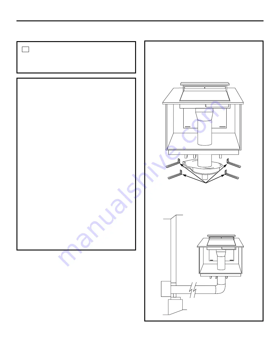
background image

OPTIONAL KITS

JXRB67

optional accessory for indoor remote

location of the blower/motor assembly. Use

this kit when the blower and motor assembly

will be located below the cabinet floor.

JXBC67

optional outdoor cover accessory 

for remote installation of blower and motor

assembly on an outside wall.

17

Installation Instructions

CONNECT THE POWER

Plug power cord into a properly grounded

receptacle.

4

INSTALL THE COOKTOP

With the downdraft in the “down” position,

place the cooktop into the cutout.

Push the cooktop back until the back edge

of the cooktop just barely touches the front

edge of the downdraft cover.

Using a dime as a thickness gauge, align

the cooktop so that there is a minimum

uniform gap of 0.05

(the thickness of 

a dime) between the cooktop and the

downdraft cover.

NOTE:

Do not force the downdraft cover to

move rearward when aligning the cooktop.

This may cause the downdraft cover to

impact and damage the cooktop when the

vent is raised and lowered.

NOTES:

Accurate alignment of cooktop and

downdraft is necessary to ensure that there

is no interference when air vent is raised

and lowered. There should be a gap of

0.05

(the thickness of a dime) between the

back edge of the cooktop and the front

edge of the downdraft cover.

Radiant cooktop cannot be flush mounted

when using this downdraft vent.

Mounting

brackets

Summary of Contents for Profile JVB67HBB

Page 1: ...for local inspector s use IMPORTANT Observe all governing codes and ordinances Note to Installer Be sure to leave these instructions with the Consumer Note to Consumer Keep these instructions for fut...

Page 2: ...or ceiling do not damage electrical wiring and other hidden utilities WARNING To reduce the risk of fire use only metal ductwork C B A IMPORTANT These vents are recommended for island installations Ag...

Page 3: ...placing cabinetry directly above the cooking surface when possible If cabinetry is used above the cooking surface Installation must conform with local codes Use cabinets no more than 13 deep Maintain...

Page 4: ...cabinets Maintain cutout clearances to front edge as specified In an island or peninsula the countertop can be extra deep to provide seating opposite of the cooktop Adding base cabinets on each side...

Page 5: ...ace Depth Minimum Setback Combined Combined Model No Width Overall Depth with Downdraft Cutout to Front Edge Cutout Width Cutout Depth JP326 30 1 4 21 1 4 23 3 8 2 1 2 28 1 2 22 3 8 JP340 JP350 29 3 4...

Page 6: ...0S 36 21 1 4 23 1 8 2 1 2 34 22 7 8 JGP962 36 20 7 16 22 9 16 2 1 2 34 21 3 4 JGP962S 36 1 8 21 1 16 23 3 16 2 1 2 34 22 1 8 Includes 1 8 gap between cooktop and vent trim Required to maintain UL or A...

Page 7: ...tric cooktop the vent must operate from a separate 120V outlet A properly grounded 3 prong receptacle should be located within reach of the vents 2 foot power cord Locate the receptacle inside the cab...

Page 8: ...Pieces Length Pieces Length Pieces Length 31 4 x 10 to 6 Round 6 Round 1 ft per 31 4 x 10 Transition 12 ft Straight foot length 45 Elbow 5 ft 90 Elbow 6 Round 31 4 x 10 1 ft per 31 4 x 10 Wall Cap 21...

Page 9: ...ng plate assembly Retain screws Remove the blower assembly turn it over to access the 4 nuts holding the blower to the mounting plate Remove the nuts IMPORTANT Do not lift the motor by the power cable...

Page 10: ...wndraft unit slots INTO the next piece of the duct Secure the joints with self tapping screws and apply duct tape around the joints to ensure an airtight seal 2 INSTALL THE DOWNDRAFT VENT Place the do...

Page 11: ...ead through the mounting bracket and countertop Press trim over the mounting bracket to set the adhesive Connect Raise Lower Wire Lead to Wire Box Thread wire end with the connector through the hole o...

Page 12: ...touches the front edge of the downdraft cover Using a dime as a thickness gauge align the cooktop so that there is a minimum uniform gap of 0 05 the thickness of a dime between the cooktop and the do...

Page 13: ...extended Press the Raise Lower switch The blower control switch Slide it to the right may be in the OFF position Vent does not rise Vent not plugged into an outlet Plug vent into a 120V power outlet R...

Reviews: