


30
″
COOKTOP/DOWNDRAFT
UNIT JVB37
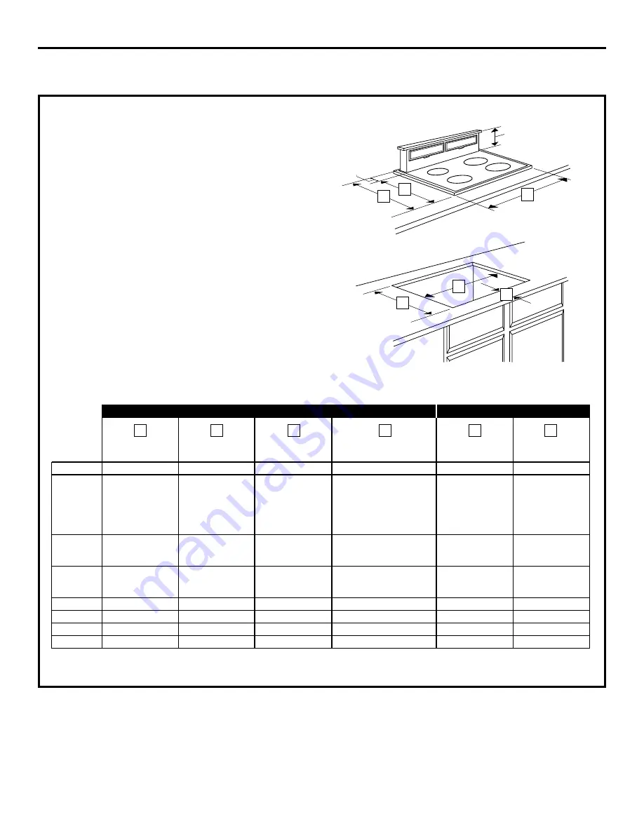
NOTE: Before you begin, measure and mark
Dimension 3 to ensure that adequate flat
countertop surface is available.
Identify the cutout illustration for the cooktop
model you are installing with this downdraft
vent system.
•
Draw lines on the countertop to follow
as a cutting guide.
•
Make sure sides of the opening are
parallel and rear and front cuts are exactly
perpendicular (right angle) to sides.
Planning Installation 30
″
Electric and Gas Cooktops with Downdraft Vents
Preparing Cutout
Overall
Cooktop Surface
Surface Depth
Minimum Setback
Combined
Combined
Model No.
Width
Overall Depth
with Downdraft*
Cutout to Front Edge**
Cutout Width
Cutout Depth
JP326
30-1/4
″
21-1/4
″
23-3/8
″
2-1/2
″
28-1/2
″
22-3/8
″
JP340
JP350
29-3/4
″
20-7/8
″
23
″
2-1/2
″
28-1/2
″
22-1/4
″
JP930
JP931
JP938
JP939
JP350SC
JP930SC
29-7/8
″
21-1/2
″
23-5/8
″
2-1/2
″
28-1/2
″
22-3/8
″
JP938SC
JGP328
JGP933
30
″
21
″
23-1/8
″
2-1/2
″
28-1/2
″
22-3/8
″
JGP933S
JGP336
30
″
21
″
23-1/8
″
2-1/2
″
28-1/2
″
22-1/4
″
JGP932
29-3/4
″
21
″
23-1/8
″
2-1/2
″
28-1/2
″
22-1/4
″
JGP930S
30
″
21-1/4
″
23-3/8
″
2-1/2
″
28-1/2
″
22-1/4
″
JGP932S
29-7/8
″
21-5/8
″
23-3/4
″
2-1/2
″
28-1/2
″
22-5/8
″
*
*Includes 1/8
″
gap between cooktop and vent trim
**Required to maintain UL or AGA approvals
6
5
4
3
2
1
10
Installation Instructions
INSTALLING THE DOWNDRAFT VENT SYSTEM
2
1
⁄
8
″
8
1
⁄
2
″
1
2
3
4
5
6


