background image

Installation Instructions

13

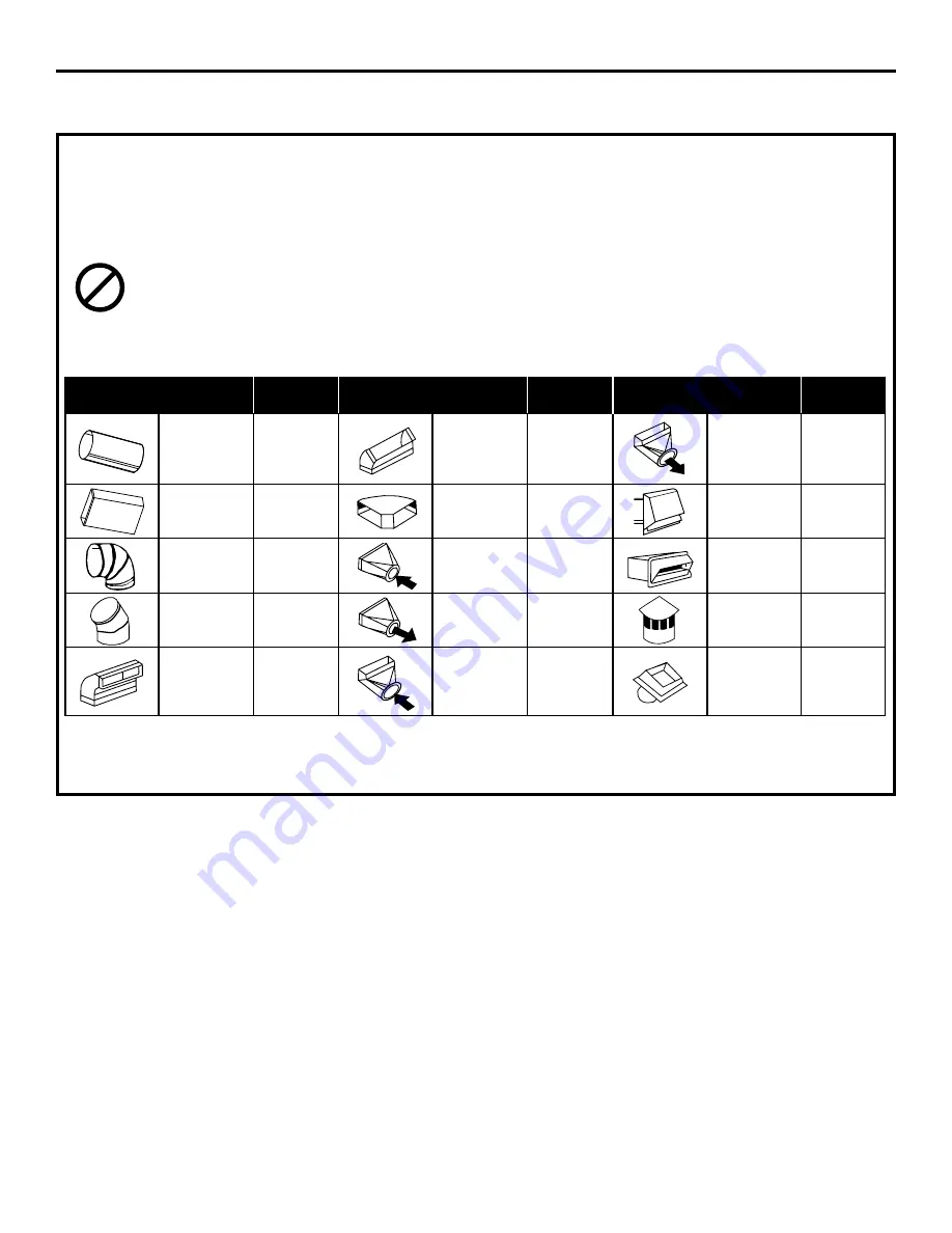
DUCTWORK LENGTH AND DUCT FITTINGS

NOTE: Do not exceed 150 foot maximum permissible equivalent lengths!

Flexible ducting: If flexible metal ducting is used, all equivalent feet values in the table should be

doubled. The flexible metal duct should be straight and smooth and extended as much as possible. 

DO NOT

use flexible plastic ducting.

Add equivalent lengths for all duct pieces and transitions used to ensure that the duct run does not

exceed the maximum 150 feet.

Duct 

Equivalent 

Duct 

Equivalent 

Duct 

Equivalent 

Pieces

Length*

Pieces

Length*

Pieces

Length*

3

1

4

x 10

to 6

Round

6

Round

1 ft. (per 

3

1

4

x 10

Transition

12 ft.

Straight

foot length)

45° Elbow

5 ft.

90° Elbow

6

Round

3

1

4

x 10

1 ft. (per 

3

1

4

x 10

Wall Cap

21 ft.

Straight

foot length)

90° Flat Elbow

24 ft.

with Damper

6

Round

3

1

4

x 10

6

15 ft.

to 3

1

4

x 10

7 ft.

Wall Cap

27 ft.

90° Elbow

Transition

with Damper

3

1

4

x 10

6

to 6

Round

5 ft.

6

Round

45° Elbow

9 ft.

Transition

Roof Cap

20 ft.

6

Round

to 3

1

4

x 10

3

1

4

x 10

Transition

20 ft.

6

Round

90° Elbow

16 ft.

90° Elbow

Roof Vent

24 ft.

SHOULD NOT EXCEED 150 EQUIVALENT FEET

*Equivalent lengths of duct pieces are based on actual tests conducted by GE Evaluation Engineering 

and reflect requirements for good venting performance. See chart for CFM Duct Length.

Summary of Contents for Profile JVB67HBB

Page 1: ...for local inspector s use IMPORTANT Observe all governing codes and ordinances Note to Installer Be sure to leave these instructions with the Consumer Note to Consumer Keep these instructions for fut...

Page 2: ...or ceiling do not damage electrical wiring and other hidden utilities WARNING To reduce the risk of fire use only metal ductwork C B A IMPORTANT These vents are recommended for island installations Ag...

Page 3: ...placing cabinetry directly above the cooking surface when possible If cabinetry is used above the cooking surface Installation must conform with local codes Use cabinets no more than 13 deep Maintain...

Page 4: ...cabinets Maintain cutout clearances to front edge as specified In an island or peninsula the countertop can be extra deep to provide seating opposite of the cooktop Adding base cabinets on each side...

Page 5: ...ace Depth Minimum Setback Combined Combined Model No Width Overall Depth with Downdraft Cutout to Front Edge Cutout Width Cutout Depth JP326 30 1 4 21 1 4 23 3 8 2 1 2 28 1 2 22 3 8 JP340 JP350 29 3 4...

Page 6: ...0S 36 21 1 4 23 1 8 2 1 2 34 22 7 8 JGP962 36 20 7 16 22 9 16 2 1 2 34 21 3 4 JGP962S 36 1 8 21 1 16 23 3 16 2 1 2 34 22 1 8 Includes 1 8 gap between cooktop and vent trim Required to maintain UL or A...

Page 7: ...tric cooktop the vent must operate from a separate 120V outlet A properly grounded 3 prong receptacle should be located within reach of the vents 2 foot power cord Locate the receptacle inside the cab...

Page 8: ...Pieces Length Pieces Length Pieces Length 31 4 x 10 to 6 Round 6 Round 1 ft per 31 4 x 10 Transition 12 ft Straight foot length 45 Elbow 5 ft 90 Elbow 6 Round 31 4 x 10 1 ft per 31 4 x 10 Wall Cap 21...

Page 9: ...ng plate assembly Retain screws Remove the blower assembly turn it over to access the 4 nuts holding the blower to the mounting plate Remove the nuts IMPORTANT Do not lift the motor by the power cable...

Page 10: ...wndraft unit slots INTO the next piece of the duct Secure the joints with self tapping screws and apply duct tape around the joints to ensure an airtight seal 2 INSTALL THE DOWNDRAFT VENT Place the do...

Page 11: ...ead through the mounting bracket and countertop Press trim over the mounting bracket to set the adhesive Connect Raise Lower Wire Lead to Wire Box Thread wire end with the connector through the hole o...

Page 12: ...touches the front edge of the downdraft cover Using a dime as a thickness gauge align the cooktop so that there is a minimum uniform gap of 0 05 the thickness of a dime between the cooktop and the do...

Page 13: ...extended Press the Raise Lower switch The blower control switch Slide it to the right may be in the OFF position Vent does not rise Vent not plugged into an outlet Plug vent into a 120V power outlet R...

Reviews: