– 35 –
NOTE:
Control display will show "LOC ON" if the
RANGE LOCK-OUT pad is touched and the cooktop
lock switch is in the closed position.
Control display will show "LOC OFF" if the RANGE
LOCK-OUT pad is touched and the cooktop unlock
switch is in the closed position.
• The word "LOC"
will
fl
ash on and off in the display
while the lock motor is in motion. When the cooktop
is locked, the words “LOC ON” remain illuminated in
the display.
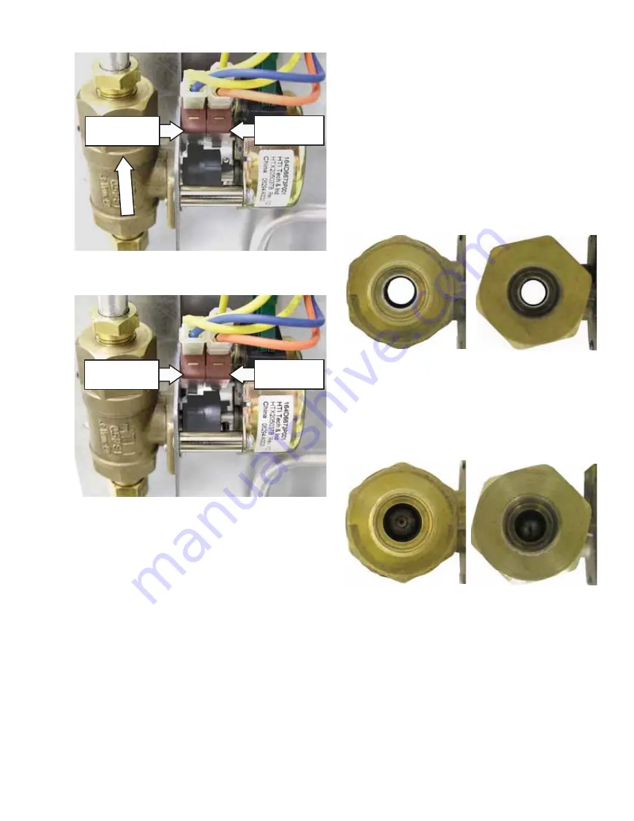
• CAM – The cam on the motor performs two
functions:
Positions the lock valve in the open or closed
1.
position.
Operates the lock switches, which tell the
2.
control if the lock valve is unlocked or locked.
The lock valve is a ball-type that rotates one
quarter turn per command. The ball placed in
the passageway (through which gas
fl
ows), has a
hole through it that enables the valve to open and
close. When the ball is positioned so that the hole
runs the same direction as the passageway, the
gas
fl
ows through the hole, and the valve is open.
However, when the ball is positioned so that the hole
is perpendicular to the passageway, the gas cannot
pass through, and the valve is closed. The ball is
controlled by the cam located outside the valve.
SWITCH POSITION- LOCKOUT VALVE OPEN
SWITCH POSITION- LOCKOUT VALVE CLOSED
BALL POSITION- LOCKOUT VALVE OPEN
INLET VIEW
OUTLET VIEW
INLET VIEW
OUTLET VIEW
BALL POSITION- LOCKOUT VALVE CLOSED
Cooktop Unlock
Switch-Closed
Cooktop Unlock
Switch-Open
Cooktop Lock
Switch-Open
Cooktop Lock
Switch-Closed
(
Continued next page
)
F
L
O
W
The lock motor has an approximate resistance value
of 2.1K
Ω
.
The resistance of the lock motor can be checked
on the ERC. Place the control panel in the service
position. (See
Touch Panel and ERC
.)
Test between N and COOK for the approximate
resistance value.

