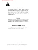
GE Appliances
General Electric Company
Louisville, Kentucky 40225
31-9145
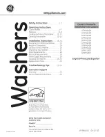
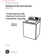
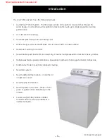
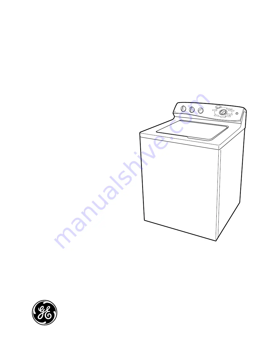
Profile Washers With
Electronic Control and
Mode Shifter Assembly
Technical Service Guide
October 2006
GE Consumer & Industrial
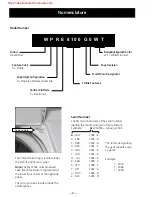
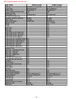
WPRE6100
WPRE8100
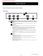
LOAD SIZE
Profile
TEMPERATURE
OPTIONS
START / PAUSE
COTTONS
CASUALS
PREWASH
HANDWASH
DELICATES
EASY CARE
SPEEDWASH