background image

– 25 –

Water Level Switch

Note:   Also refer to Water Level (Load Size) Diagnostic.

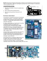
The water level switch has two switches in one housing and is
located inside the control panel.  The water level switch is
connected by a hose to an air reservoir near the bottom of the outer
tub.  When the water level rises in the washer tub, air is trapped in
the reservoir.    As the water level rises, the air pressure in the
reservoir increases.  When 6 inches of water have accumulated in
the washer tub, the appropriate pressure will be achieved and the
low switch will open.  The high switch will open when the water in
the tub has reached its maximum level.  Mid-level fills are timed,
based on the amount of time it took to fill to lowest level.

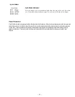
This Profile model is equipped with a flood protection feature.  If the low level pressure switch is
opened while the washer is in idle mode, the electronic control will activate the drain pump to extract
any water in the tub.  The rate of water extraction during flood protection exceeds the rate of fill under
normal conditions.  The pump will continue to operate for 60 seconds after the low level switch has
closed.

Water Level (Load Size) Diagnostics

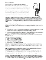
To determine if the water level switch and electronic control board are functioning correctly, perform the
following:

1. Place the unit in service mode.

2. Index to the Low Level Pressure Switch test and press start.  The washer will fill with water until the

low level pressure switch opens at the extra low level, approximately 6.1 inches.

3. Index to the High Level Pressure Switch test and press start.  The washer will fill with water until the

high level pressure switch opens at the giant level, approximately 14 inches.

Note: It will be necessary to shut the lid in order to reset the electronic control board and advance to
the next water level.

Each load size should be at the following level:

Giant - 14.0 (+/- 0.5) inches, 26.3 gallons

Large -  12.5 (+/- 0.5) inches , 23.1 gallons

Medium - 10.4 (+/- 0.5) inches,  19.9 gallons

Small -  8.2 (+/- 0.5) inches, 16.8 gallons

Extra Small - 6.1 (+/- 0.5) inches, 13.6 gallons

If the water level of an Extra Small Load is deeper than 6.1 (+/- 0.5) inches, check to see that the water
level switch is closed when the water level is below 6.1 (+/- 0.5) inches and that it is open when the water
level is 6.1 (+/- 0.5) inches and above.  If the water level sensor functions properly, replace the electronic
control board.

Note: Small, Medium, and Large Load Size water levels are timed in the electronic control board.  The
timing is based on the amount of time it takes to fill to the lowest level.

If the water level of a Small, Medium, or Large Load is deeper than 8.2 (+/- 0.5) inches (Small), 10.4
(+/- 0.5) inches (Medium), or 12.5 inches (Large), check to see that the Extra Small Load water level is
operating normally (see above paragraph).  If the Extra Small Load operates normally, replace the
electronic control board.

If the water level of a Giant Load is deeper than 14.0 (+/- 0.5) inches, check to see that the water level
switch is closed when the water level is below 14.0 (+/- 0.5) inches, and that it is open when the water level
is 14.0 inches and above.  If the water level sensor is functioning properly, replace the electronic control

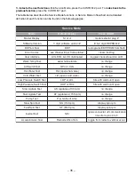
4

J10

J8

+12V

PRESSURE SWITCH HIGH

PRESSURE SWITCH LO

W

COM

11

HI
16

LOW

12

WATER

LEVEL

SWITCH

3 2 1

Summary of Contents for Profile WPRB9220

Page 1: ...C PUB 31 9095 10 02 MODEL SERIES WPRB9250 WPRB9220 TECHNICAL SERVICE GUIDE GE Consumer Home Services Training Profile Stainless Steel Washer ...

Page 2: ...personal injury disconnect power before servicing this product If electrical power is required for diagnosis or test purposes disconnect the power immediately after performing the necessary checks RECONNECT ALL GROUNDING DEVICES If grounding wires screws straps clips nuts or washers used to complete a path to ground are removed for service they must be returned to their original position and prope...

Page 3: ...1 Drain Pump 18 Drive Belt 18 Electronic Control Board 26 Error Codes 40 Flood Protection 11 Front Panel 17 Inverter 29 Leveling Legs 16 Lid Lock 23 Lid Switch 22 Lid Switch Diagnostics 23 Motor 28 Motor TachogeneratorTest 32 Nomenclature 2 Problem Chart 46 Schematic 47 Serial Number 2 Service Mode 34 Speed Sensor 29 Spin Basket 19 Suspension 20 Transmission 21 Troubleshooting Guide 42 Tub With Mo...

Page 4: ...k Splash Color The first two characters of the serial number identify the month and year of manufacture Example AD123456S January 2002 A JAN 2005 H D FEB 2004 G F MAR 2003 F G APR 2002 D H MAY 2001 A L JUN 2000 Z M JUL 1999 V R AUG 1998 T S SEP 1997 S T OCT 1996 R V NOV 1995 M Z DEC 1994 L The letter designating the year repeats every 12 years Example T 1974 T 1986 T 1998 Note Model number and ser...

Page 5: ...ple your receipt here Proof of the original purchase date is needed to obtain service under the warranty One Year Any part of the washer which fails due to a defect in materials or workmanship During this full From the date of the one year warranty GE will also provide free of charge all labor and in home service to replace the original purchase defective part Two Years Any part of the washer whic...

Page 6: ... 4 Control Features WPRB9250 WPRB9220 ...

Page 7: ...UICK RINSE is found under the WASH CYCLES menu SPEED WASH For lightly soiled items that are needed in a hurry Cycle time is approximately 20 minutes depending on your household water pressure START After you have selected a new cycle press once to start the cycle Press twice to select the last cycle used and start the washer If the washer is running press once to pause the cycle press again to con...

Page 8: ...asher beeps to store your selection To recall your stored combination Press the CUSTOM 1 or CUSTOM 2 pad then press START To reprogram the custom settings Repeat steps 1 4 above DRAIN SPIN You can drain and spin any cycle at any time On models with a DRAIN SPIN pad press to drain and spin On models without a DRAIN SPIN pad press START to pause the washer select DRAIN SPIN from the WASH CYCLES menu...

Page 9: ... washer settings for the optimum cycle to remove the stain Select the wash garment or stain cycle by pressing the arrow pads at the sides of the display You can scroll up and down through the list of cycles by pressing the UP and DOWN arrow pads beneath the display NOTE Any time you make a selection that is incompatible with the chosen wash cycle the washer will beep twice Change any of the automa...

Page 10: ...TE Any time you make a selection that is incompatible with the chosen wash cycle the washer will beep twice Change any of the automatic settings if desired by pressing the pad beneath the setting Higher settings will Fill the washer basket with more water Remove heavier soil The highest level is the Stain Wash cycle with a 30 minute soak and agitation at the beginning of the wash cycle Add cold wa...

Page 11: ...c out of clothes DRAIN Spin Only Drain and spin any cycle at any time SPIN SOAK Medium Provides a soak of up to 24 hours The washer will drain and spin at the end of the cycle SPEED WASH Medium Fast For lightly soiled items that are needed in a hurry Cycle time is approximately 20 minutes depending on your household water pressure The Wash Cycles are optimized according to load type The chart belo...

Page 12: ...rue handwash for all of your delicate washables Cycle Options SIGNAL Alerts you when the cycle is complete Press SIGNAL to select low medium or high volume or to turn the beeper off 2ND RINSE Adds a second cold rinse to any cycle WARM RINSE Changes the final rinse of a wash cycle from a cold to a warm rinse DELAY START Use to delay the start of your washer Choose your wash cycle and any options Pr...

Page 13: ...ump to extract any water in the tub The rate of water extraction during flood protection exceeds the rate of fill under normal water conditions The pump will continue to operate for 60 seconds after the low level switch has closed On some models cycle status indicator lights show what part of the cycle the washer is in On models without indicator lights the cycle status will show in the display Cy...

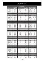
Page 14: ... d e M m r a W t s a F m u i d e M y n A r a e W y a d y r e v E e g r a L m u i d e M t o H t s a F m u i d e M y n A s l e w o T t n a i G t h g i L t o H t s a F y n A s t e e h S t n a i G m u i d e M t o H t s a F m u i d e M y n A s g u R s t a M m u i d e M y v a e H m r a W t s a F m u i d e M y n A n e n i L e l b a T m u i d e M n i a t S m r a W m u i d e M y n A r a e W t n a f n I e g...

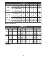
Page 15: ... 1 0 0 1 M P S e t u n i M r e P s e k o r t S s e m i T n o i t a t i g A l i o S t h g i L l i o S m u i d e M l i o S y v a e H l i o S n i a t S e l c y C e s a h P b u S s n o i t i t e p e R e t a t i g A k a o S e t a t i g A k a o S e t a t i g A k a o S e t a t i g A k a o S e s n i R n o t t o C l a i t i n I 1 0 6 3 0 0 6 3 0 0 6 3 0 6 3 0 6 3 0 0 8 1 n w o D p e t S 1 0 8 1 0 0 6 3 0 0...

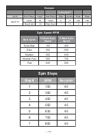
Page 16: ... p e t S 0 3 n w o D p e t S 1 5 7 0 0 M P R d e e p S n i p S e l c y C n i p S n i p S e t a c i l e D d e e p S n i p S n o t t o C d e e p S w o l S a r t x E 0 5 1 0 5 4 w o l S 0 5 3 0 5 5 m u i d e M 0 5 4 0 3 6 t s a F m u i d e M 0 5 5 0 0 7 t s a F 0 3 6 0 5 8 s p e t S n i p S p e t S M P R s d n o c e S 1 0 5 1 5 4 2 0 5 3 5 4 3 0 5 4 5 4 4 0 5 5 5 4 5 0 3 6 5 4 6 0 0 7 5 4 7 0 5 8 5 4...

Page 17: ...Accelerometer Drain Pump Inverter Leg and Platform Assembly Speed Sensor Belt Transmission Behind Motor Choke Water Valve Water Valve Electronic Control Board Electronic Control Board Water Level Switch Water Level Switch Control EMI Filter Control EMI Filter ...

Page 18: ...ill set rear legs to correspond to the front settings Gently set the washer back down Control Panel To place the control panel in the service position 1 Remove 4 screws from the rear of the control panel 2 Gently pull on each corner to unsnap the control panel from the sides of the unit Washer Components P0003576 3 Rotate the control panel forward approximately 1 inch and slide to the right to unl...

Page 19: ...tch Bottom Tabs Lid Switch Cover Lid Assembly The cover lid assembly is fastened at the front by 2 screws on the sides by 2 metal catches and at the back by 3 locking tabs which protrude from the bottom of the control panel Note Do not allow lid to swing open when cover lid assembly is removed Damage may result To remove the cover lid assembly 1 Remove the front panel and control panel see Front P...

Page 20: ...his model is equipped with flood protection If the low pressure switch opens while the washer is in idle mode the electronic control board will activate the drain pump Pump operation will continue for 60 seconds after the low level switch closes The drain pump is coupled to a 120 VAC 60 Hz 85 watt motor The pump will operate independently of other mechanical components and will evacuate water at v...

Page 21: ...e of Stainless Steel and must be torqued to 150 ft lbs If the hub nut is removed it must be tightened to 150 ft lbs If the hub nut wrench PN WX5X1325 is used to tighten the hub nut the wrench must be struck with a rubber mallet or dead blow hammer until it will not tighten any further This may take 30 to 50 hits with a rubber mallet or dead blow hammer To be certain that the nut will not tighten a...

Page 22: ...he tub with motor and transmission on its side and slide tub out of the unit Suspension The tub and motor assembly spin basket tub motor transmission and leg and platform assembly is suspended by four rod and spring assemblies The rod and spring assemblies are attached to each corner of the cabinet They extend down and connect to the leg and platform assembly This arrangement provides limited move...

Page 23: ...ove the transmission drive pulley by holding the belt and removing the 3 4 in pulley nut Remove Pulley Nut Squeeze Belt 3 Remove 4 3 8 in bolts mounting the transmission to the leg and platform assembly 4 Remove 4 1 2 in hex bolts securing the leg and platform assembly to the tub and remove the leg and platform assembly 5 Lift the transmission up and out of the tub 6 Remove the speed sensor and ma...

Page 24: ...then pull the bottom of the tub assembly out of cabinet Lid Switch Note Also refer to Lid Switch Diagnostic The lid switch is fastened to the cover lid assembly by a single latch It is a safety feature that prevents the machine from agitating or spinning when the lid is open The switch is closed by a magnet that is attached to the lid When the lid is shut the magnet will cause the switch to close ...

Page 25: ...rs the speed sensor for transmission rotation When 50 rpm is sensed the electronic control board will energize the lid lock with 12 VDC locking the lid The lid lock will remain energized until the electronic control board determines that the basket has stopped spinning Should the lid lock fail and the lid switch be opened during spin for more than 5 seconds the electronic control will limit high s...

Page 26: ...voltage sent to the water temperature sensor and voltage returning from the water temperature sensor to determine the temperature of the incoming water and to make ATC decisions TheATC should maintain the water temperature in the tub within the ranges specified in the Water Temperatures chart by opening or closing the hot and cold water valves To prevent sudden water temperature changes on consume...

Page 27: ...High Level Pressure Switch test and press start The washer will fill with water until the high level pressure switch opens at the giant level approximately 14 inches Note It will be necessary to shut the lid in order to reset the electronic control board and advance to the next water level Each load size should be at the following level Giant 14 0 0 5 inches 26 3 gallons Large 12 5 0 5 inches 23 1...

Page 28: ... all washer functions The boards are replaced with the control panel as an assembly Avoltage reading between 4 5 and 5 5 VDC should be measured at connector J2 between pin 3 V sense and pin 2 sensor ground Avoltage reading greater than 5 5 VDC indicates a faulty electronic control board Avoltage reading lower than 4 5 indicates one of the following Faulty electronic control board faulty wire harne...

Page 29: ... equipped with a conductive noise filter Should interference with electronic items be reported suspect a problem with the filter The ground wire attached to the bottom of the filter must have a good connection for the filter to operate properly Check to make certain that the ground wire is connected properly before replacing the filter The filter is accessed by placing the control panel in the ser...

Page 30: ...tachogenerator which produces voltage when the motor shaft is rotated This voltage is monitored by the inverter to determine motor speed The inverter makes speed adjustments as necessary based on this information The inverter adjusts motor torque as necessary to start the motor therefore a clutch is not required A 45 second ramp up time can be expected at the start of agitate or spin Note Terminal...

Page 31: ...trophic brake failure has occurred The unit will immediately be disabled and will display error code E43 on the Digital Seven Segment Display DSSD The unit will power up but no cycle selection will be available The unit will remain disabled until the error code is reset using service mode Inverter The inverter converts line in single phase 60 Hz 120 VAC into 3 phase varying frequency 230 VAC The i...

Page 32: ...acceleration and transmits this information to the electronic control board The electronic control board uses this information to monitor and control the spin basket for an out of balance condition during spin If an out of balance condition is detected the electronic control board will reduce the spin rpm If after lowering the speed an out of balance condition is still detected the control will ag...

Page 33: ... connector from J10 cutting off as close to the main wiring harness as possible and dispose 4 Put on EMI wristband and clip onto any bare metal part of the unit or touch any bare metal part of the unit with your hand to discharge any static electricity 5 Remove the screw securing the accelerometer to the front bottom of the tub Push it down and off the tub 6 Cut the wiring of the old accelerometer...

Page 34: ...ll the way to the control panel Tape the accelerometer wires to the washer harness by applying tape every 6 inches 11 Plug in the new accelerometer connector 12 Reconnect power and check operation using service mode Motor Tachogenerator Test Perform the following to test the tachogenerator 1 Unplug the washer and remove the front panel 2 Disconnect harness connector CN10 from the inverter 3 Remove...

Page 35: ... 33 Notes ...

Page 36: ...he POWER and the STARTpads for 3 seconds When Service Mode is entered the control panel will display model code Service Mode can be exited in 4 ways 1 Press the STOP pad 2 Press the POWER pad 3 Unplug the unit 4 30 minute timeout Service Mode Enter Service Mode Exit Service Mode Restore power to the unit Within 30 seconds of power up simultaneously press and hold the POWER and START pads for 3 sec...

Page 37: ...r u t a r e p m e t r e t a w e g n a h c o n t s e T h c t i w S d i L S L C r o n P O e g n a h c o n t s e T r e t a W t o H e v l a v t o h s n e p o t o H e g n a h c o n t s e T r e t a W d l o C e v l a v d l o c s n e p o d l c e g n a h c o n t s e T h c t i w S e r u s s e r P w o L L C L r o P O L n e p o l i t n u m r a w h t i w s l l i f t s e T h c t i w S e r u s s e r P h g i H L ...

Page 38: ...vel EEPROM Test Displays EEP Press START pad to reprogram EEPROM Successful reprogramming is confirmed by beep Software Version Displays software version Press START to displays EEPROM Model Display Displays Model version Press START to display model plug Slow Spin Test Activates 150 rpm spin Press START to display rpm Fast Agitate Test Activates 155 spm agitate Slow Agitate Test Activates 30 spm ...

Page 39: ...ng this test the most recent error code recorded in the fault log will be displayed on the DSSD If no errors are recorded in the fault log E00 will be displayed Pressing the STARTpad will clear any displayed error codes from the fault log and will cause the next most recent error code recorded to be displayed After clearing all errors from the fault log the appliance shall display E00 on the DSSD ...

Page 40: ...ed and the high pressure switch indicates open during this test the washer will turn on only the highest level on the load size icon The washer will turn off the hot water valve and the cold water valve as the test is exited High Pressure Switch Test The High Pressure Switch Test will verify operation of the high pressure switch Upon entering the test the state of the high pressure switch will be ...

Page 41: ... to the inverter and test signals will be sent on the inverter communication lines to provide a means to isolate a Power CommunicationError If the STARTpad is pressed during this test the washer will cycle the inverter communication lines see figure below Each time you touch START you should toggle between a positive and negative voltage that should read greater than 1 volt Accelerometer Test This...

Page 42: ...using the CUSTOM 1 pad If no errors are present E00 will be displayed on the DSSD If an error code is present the error code will display immediately If there is more than one error pressing STARTwill clear the displayed error code from the fault log and cause the next most recent error to be displayed To clear all error codes continue to press the STARTpad while in the Error Codes function Note C...

Page 43: ...SD Variable Speed Drive Heat Sink Over Temperature Check inverter could have been a very large load or jammed agitator in wash cycle E48 Drive System VSD Motor Short Circuit Check motor resistance check inverter to motor harness E49 Drive System VSD Variable Speed Drive Drive Overload Check inverter could have been a very large load or jammed agitator in wash cycle E4A Drive System VSD Variable Sp...

Page 44: ... may be indicated Lint or residue on Clothes are air or line dried If you do not dry your clothes with a clothes dryer your clothes clothes may retain more lint Incorrect sorting Separate lint producers from lint collectors Washing too long Wash small loads for a shorter time than larger loads Detergent not dissolving Add detergent as wash basket fills with water before you load clothes Try a liqu...

Page 45: ... Wash in warm or cold water water that is too hot OPERATION Possible Causes What To Do Washer pauses in cycle The ULTRA HANDWASH This is normal The washer alternates between agitate DELICATES or CASUALS and soak during the ULTRA HANDWASH DELICATES and cycle was chosen CASUALS cycles to get your clothes cleaner with less wear The highest SOIL LEVEL The highest SOIL LEVEL setting adds a 15 minute se...

Page 46: ...y connected hoses are connected to correct faucets Water valve screens are Turn off the water source and disconnect water fill stopped up hoses from the upper back of the washer Use a brush or toothpick to clean the screens in the machine Reconnect the hoses and turn the water back on House water heater is Make sure house water heater is delivering water not set properly at 120 F 140 F 48 C 60 C P...

Page 47: ...ll yellow tag and in unit attached rod from the bottom right hand side of washer Washer is sitting too close Pull washer away from the wall about 4 11 cm to wall causes knocking is needed during cycle PerfecTemp Plus feature This is normal PerfecTemp Plus turns water valves off is being used and on to adjust water temperature OTHER Possible Causes What To Do Labels on the exterior Occasionally the...

Page 48: ... f I e g a k c o l b r o f g n i n n i p s t o n s i r e h s a W r e t r e v n i r o r o t o m y t l u a F t r a h c w o l f c i t s o n g a i D e t a r e p O t o N s e o D r o t o M e e S g n i t a t i g a t o n s i r e h s a W h c t i w s d i l y t l u a F g n i r i w h c t i w s d i l r o h c t i w s d i l y t l u a F c i t s o n g a i D h c t i w S d i L o t r e f e R g n i t a t i g a t o n s...

Page 49: ... 3 2 CN8 J6 1 2 50K Ohms at 77 F WATER TEMPERATURE SENSOR ANALOG GND THERMISTOR J2 5 4 RS485 B 2 V SENSE 1 SENSOR GND 3 RS485 A U ACCELEROMETER 1 2 3 4 V SENSE VERTICAL ACCL RADIAL ACCL SENSOR GND 5 J10 4 J3 DIGITAL GND 1 12 V 2 ACC 3 3 2 1 SPEED SENSOR 1 2 3 V SENSE SENSOR GND 4 SPEED SIGNAL J20 EARTH GND YR CX VX YB RX WX YX BX WX BX RX VX WX BX RX WX BX NX RX WR NW RB BX TX VX YELLOW RED BLUE W...

Reviews: