– 32 –
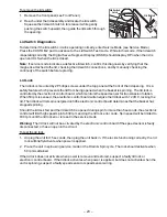
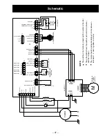
Terminal 6
Terminal 5
GEA01273
1
2
3
4
5
6
CN9
CN10
CN8
Terminal 4
6
2
1
3
Note: Proper tachogenerator resistance should
be 190
Ω
+/- 10% between terminals 4 and 5.
Terminal 5
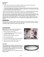
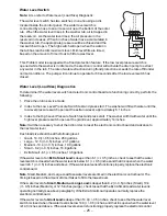
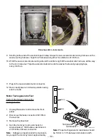
9. Starting at the end of the section taped in step 8, tape the new accelerometer wiring harness on the
washer wiring harness. Tape the 2 harnesses together for a distance of 4 inches.
10. Wind the new accelerometer wiring around the entire length of the washer wire harness, all the way
to the control panel. Tape the accelerometer wires to the washer harness by applying tape
every 6 inches.
11. Plug in the new accelerometer connector.
12. Reconnect power and check operation using
service mode.
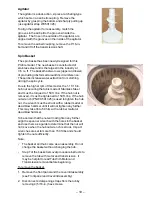
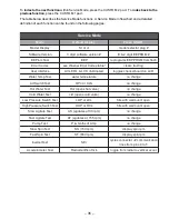
Motor Tachogenerator Test
Perform the following to test the
tachogenerator:
1. Unplug the washer and remove the front
panel.
2. Disconnect harness connector CN10 from
the inverter.
3. Remove the drive belt.
4. Spin the motor by hand, and check for
approximately 1 VAC between terminals 4
and 5 of the harness connector.
Note: Voltage is proportional to the motor rpm.
As you spin the motor by hand, approximately
Place tape at 6 in. increments.
Summary of Contents for Profile WPRB9220
Page 6: ... 4 Control Features WPRB9250 WPRB9220 ...
Page 35: ... 33 Notes ...

