background image


Nuova Via di Piano Comprensorio Vulcano 

Sesto San Giovanni, MI 20099 Italy 

Tel. 02-24105.001 


IS 2653 GB


Page 

5

 of 

18


Transport and storage conditions 

 
The  bushing  is  shipped  in  a  wooden  box  suitable  for  marine  transport,


designed  to  provide  protection  of  the 

bushing in accordance with the specified transport conditions. 
 
The complete crate must be lifted, loaded on vehicles and transported with great care to prevent damages of 
the  bushing  or  its  accessories.  Centre  of  gravity  and  lifting  points  are  painted  on  the  crate walls, stacking of 
crates is not allowed. 
 
Shock  indicators  of  suitable  sensitivity  are  fixed  on  the  crate  walls.  They  turn  the  status  when  the  shock 
exceeds the indicator trigger level. 
 
GE Grid Solutions RPV will not respond of any damage due to un-proper operations. Removal or damage of 
the shock recorders will cause the interruption of the warranty. 
 
 
3.1 

Transport conditions 

 
The bushing can be transported by truck, ship, airplane. 
In  order  to prevent dangerous movement of the crate during the transport, it is responsibility of the transport 
company to carefully fix it on the vehicle by suitable retain systems like ropes, synthetic pulling bands or any 
other method. 
The maximum allowed transport acceleration along the three axis is 3g (29.43 m/s

2

). In case of transport by 

truck along very bad roads (‘bumpy roads) the speed must be adequately reduced to max 30 km/h. 
Trucks to be used for road transportation must have a platform of sufficient dimensions to accommodate the 
overall crate. Crate overhang from any platform and hauling are not allowed. 
 
During  the  transport  by  road  or  ship  the  good  must  be  protected  from  rain,  sea  water  and  other  exceptional 
environment conditions by tarpaulins, not provided by GE Grid Solutions RPV, suitable to full cover the crate. 
Sea transportation on the ship main deck is not allowed.  
 
3.2 

Lifting conditions 

 
The crate can be lifted by two cranes. The lifting points are indicated on the crate and are reinforced by steel 
plates (see 

Figure 1

). Lifting by fork lift is not allowed. 


Figure 1 – Example of two crane lifting arrangement 


Lifting operation must be done by qualified operators and with certified ropes and equipment. 

Summary of Contents for PWHS

Page 1: ...pany name udated 07 07 2016 AF LP 3 Storage and transport conditions updated 22 08 2016 AF LP IS 2653 GB GE Proprietary Information Class III Confidential Export Controlled U S Government approval is required prior to export from the U S re export from a third country or release to a foreign national wherever located GAS FILLED HV WALL BUSHING PWS PWHS OPERATING AND MAINTENANCE INSTRUCTIONS ...

Page 2: ...3 3 Storage conditions 6 4 Technical characteristics 6 5 Bushing preparation and installation 7 5 1 Controls at the arrival 7 5 2 Bushing unpacking 8 6 Gas SF6 characteristics and gas filling instruction 10 6 1 Gas first filling operation and control of alarm and tripping signals 11 6 2 Gas refilling during the bushing normal operation 11 7 Gas density monitor 13 8 Power factor taps 14 9 Composite...

Page 3: ...voltages above 1000V 2 Safety In this document important safety requirements are highlighted by the word CAUTION and important operative instructions are evidenced by the word NOTE This manual must be available to the personnel responsible of the installation operation and maintenance of the bushings The wall bushing is a high voltage AC DC device filled under pressure with SF6 gas that has to be ...

Page 4: ...personnel involved in wall bushing assembly All problems detected during the bushing installation must be reported to the Foreman and to GE Grid Solutions RPV Supervisor The bushing is a pressurized device Operations on the valves pressure gauges pipes protective devices must be performed by qualified operators with the proper equipment and respecting the instructions of this manual Foreman and op...

Page 5: ...ent of the crate during the transport it is responsibility of the transport company to carefully fix it on the vehicle by suitable retain systems like ropes synthetic pulling bands or any other method The maximum allowed transport acceleration along the three axis is 3g 29 43 m s2 In case of transport by truck along very bad roads bumpy roads the speed must be adequately reduced to max 30 km h Tru...

Page 6: ...ned and tested in accordance with the IEC 62199 and IEC 60137 standard Each section is based on A composite insulator with silicone sheds The internal shielding arrangement An internal aluminium tube conductor The top flange with the line terminal The top toroidal electrical shield The two sections joined by the central flange make the complete bushing The sealing joints between the parts are desi...

Page 7: ...t the arrival Before proceeding with the unpacking operation it is necessary to perform the following controls Check the wooden crate status Check the external visual impact recorder s Open the crate and inspect packaging and goods inside see next paragraph 5 2 Check the pressure of the gas inside the bushing that must be 0 11 MPa abs 0 1 bar gauge see Figure 3 Check the composite insulators statu...

Page 8: ...supports and it is locked by locking belts Additional intermediate belts support the composite insulator to a wooden structure Figure 4 Bushing crate inside view Figure 5 Bushing inside the crate top view The transport box can be lifted by a suitable crane After the opening of the crate the visual inspection of the bushing and the removal of the locking ropes and locking blocks the bushing can be ...

Page 9: ...low the steps indicated into the provided erection and installation manual IS 2654 GB Figure 7 Example of bushing extraction and lifting CAUTION The two composite insulators are protected by a PE plastic foils Remove the protection only after the installation of the bushing on the wall and just before the energizing CAUTION To lift the bushing do not wrap ropes i e tie lifting method around the si...

Page 10: ...mium Supplier The minimum requirement is that the characteristics will be in accordance with the data listed in the GE RPV limits column The gas filling must be performed with an equipment that prevents dispersion of the SF6 gas in the atmosphere As an example next Figure 8 shows a gas plant manufactured by the German company DILO GmbH Figure 8 Vacuum filling gas plant DILO and connecting valves N...

Page 11: ...re up to 0 2 MPa abs 1 bar gauge Pressure must be directly measured on the gas density monitors installed on the bushing flange Check all the gas seals for leakages with a suitable SF6 leak meter device In case of significant leakages stop activities and contact GE Grid Solutions RPV supervisor If the bushing does not show any leakage gradually increase the pressure at the rated filling pressure v...

Page 12: ... the DILO machine check that the machine set up is for gas filling and that the connecting pipe is full of SF6 In the case of direct filling from the bottle check that the bottle is effectively charged with SF6 that the gas quantity is sufficient for the re filling the pressure reduction unit and the pipe are compatible with the DILO filling system and all equipment is specific for SF6 filling app...

Page 13: ...cation on the scale is expressed in MPa absolute referred to a gas temperature of 20 C This means that the instrument converts the gas density into a value of pressure referred to 20 C independently for the effective temperature of the gas The instrument reading practically does not change with the gas temperature that is a function of the bushing loading condition and ambient temperature Changing...

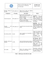
Page 14: ...epair procedure is described into the component manual see reference in the summary prepared for the specific wall bushing The composite manufacturer can provide a repairing kit and also a technical support for the repairing activity Useful indications about the composite insulator maintenance plan main actions are shown in Table 2 CAUTION Severe electrical shock risks deriving by the fact that th...

Page 15: ... the camera must be properly set in order to avoid false signals and background noise In addition an infrared scan on the line terminal and the incoming cables can reveal incipient hot spots phenomenon that can evolve into a serious damage on the electrical connection and then of the bushing itself In case of significant variation of the UV and IR emission plan the following actions UV emission Im...

Page 16: ... Gas valves electrical equipment and connecting cables When plant is off Clean the cubicle Check for gas leaks Check functionality of pressure gauge and DILO Type valves Check terminal blocks wiring cables and cable glands Check and clean the junction box Check all gas joints to the DILO Type valves on the bushing Check the cables and the cable tray to the bushing Current terminals When plant is o...

Page 17: ...pect the closure cap and the fixing screws CAUTION Do not remove the closure cap and do not touch the disk when the bushing is filled with gas An explosion of the disk could be very dangerous Gas density monitor 5 years Check calibration and operation of micro switches Check the effective and correct operation of the alarms tripping signal chain from the instruments to the substation systems Bushi...

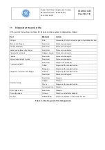
Page 18: ...electric terminals Copper silvered Dismount and recycle Toroids Aluminium Dismount and recycle Internal electrostatic shields Aluminium Dismount and recycle Transport supports Aluminium Recycle the aluminium Teflon Dispose or thermo destruction Composite insulators with flanges Fibreglass Dispose or thermo destruction Silicone Dispose or thermo destruction Aluminium Dismount and recycle Electrical...

Reviews: