background image

56 

GFK-2847W


For public disclosure


QuickPanel


Operator Interface User 

Manual


QuickPanel

+


Operator Interface 


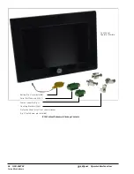
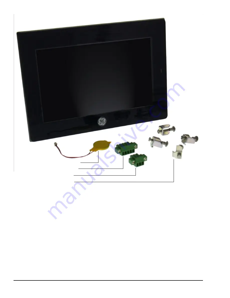
Battery (Qty 1) (pre- installed) 


Serial Port Connector (Qty 1) 


Power Connector (Qty 1) 

Mounting Brackets (Qty 4) 

Protective  Sheet (Qty 1) (not  shown) Gasket 

( Qty 1) (not  shown, pre- installed) 

IC755CxWxxCDx Example Package Contents


Summary of Contents for QuickPanel+ IC755CxS06RDx

Page 1: ...K 2847W QuickPanel Operator Interface User Manual Dec 2017 IC755CxS06RDx 6 Display IC755CxW07CDx 7 Display IC755CxS10CDx 10 Display IC755CxS12CDx 12 Display IC755CxS15CDx 15 Display For public disclosure ...

Page 2: ...y have patents or pending patent applications covering subject matter in this document The furnishing of this document does not provide any license whatsoever to any of these patents Public This document is approved for public disclosure GE provides the following document and the information included therein as is and without warranty of any kind expressed or implied including but not limited to a...

Page 3: ... used in hazardous location installations for 7 Display units Acronyms and Abbreviations ARM Advanced RISC Machine BBSRAM Battery backedSRAM DRAM Dynamic Random Access Memory FG Frame Ground FTP File Transfer Protocol GND Ground GUI Graphical user interface HTTP HyperText Transfer Protocol LCD Liquid Crystal Display LED Light emittingDiode MIB Management Information Base or Database OS Operating S...

Page 4: ...dure or condition that if not strictly observed could result in personal injury or death Caution Indicates a procedure or condition that if not strictly observed could result in damage to or destruction of equipment Attention Indicates a procedure or condition that should be strictly followed to improve these applications ...

Page 5: ...ast and Africa EMEA Online Technical Support http support ge ip com Phone 800 1 433 2682 EMEA Direct Dial 420 23 901 5850 if toll free 800 option is unavailable or dialing from a mobile telephone Technical Support Email support emea ip ge com Customer Care Email customercare emea ip ge com Primary languages of support English French Italian Czech Spanish Germany Online Technical Support http suppo...

Page 6: ...6 GFK 2847W For public disclosure QuickPanel Operator Interface User Manual Notes ...

Page 7: ...kPanel OS Utilities Settings Tool 29 3 9 1 Firmware Upgrade 30 3 9 2 Firmware Upgrade for Specific Build Version 32 3 9 3 Bypass Startup Programs 33 3 9 4 Reset Enhanced Security 35 3 9 5 Enable or Disable SNMPAgent 36 3 10 Display Screen Sensitivity Tool 38 3 11 Launch Application 39 3 12 VNC Server 40 3 13 Battery Life Prediction 41 3 14 Simple Network Management Protocol SNMP 45 3 14 1 Configur...

Page 8: ... USB Ports 84 5 7 5 Audio LINE OUT Details for IC755CxS06RDx IC755CxW07CDx and IC755CxSxxCDx 85 5 7 6 Audio MIC IN Details Only Applicable to IC755CxS06RDx and IC755CxW07CDx 85 5 7 7 SD Card Slot and Storage 86 6 Operation 89 6 1 Touchscreen Display 89 6 1 1 Display Brightness Adjustment 89 6 1 2 Display Backlight Configuration 90 6 1 3 Touchscreen Re calibration 91 6 2 Keyboard Configuration 92 6...

Page 9: ... connect to most industrial equipment using the QuickPanel communications ports The QuickPanel is equipped with several memory types to satisfy the most demanding applications A section of Dynamic Random Access Memory DRAM is split between the operating system an object store and application memory Additionally a section of Non volatile Random Access Flash Memory NOVRAM functioning as a virtual ha...

Page 10: ...e Analog Resistive Multi touch Single touch Communications Ethernet Port 1x10Base T 100Base TX Serial Port 1x RS 232C COM1 5 pin connector USB Host 2x USB 2 0 Type A maximum power 5 Vat 0 5 A USB Device 1x USB 2 0 mini Type B Storage 1x SD SDHC card slot Audio 1x Mic In Mono 3 5 mm jack 1x Line Out Stereo 3 5 mm jack Noise Immunity Noise Voltage 1500 V p p Pulse Duration 1µs Rise Time 1ns Input po...

Page 11: ...cations Ethernet Port 1x 10 100Base T RJ 45 Serial Port 1x RS 232 UART port 5 pin connector USB Host 2x USB 2 0 Type A maximum power 5 Vat 0 5 A USB Device 1x USB 2 0 mini Type B Storage 1x SD SDHC card slot Audio 1x Mic In Mono 3 5 mm jack 1x Line Out Stereo 3 5 mm jack Noise Immunity Noise voltage 1500 V p p Pulse duration 1µs Rise time 1ns Input power Rated Voltage 24 V dc 20 3 pin connector Po...

Page 12: ...Two point Communications Ethernet Port 2x 10 100Base T RJ 45 Serial Port 1x RS 232 UART port 1x RS 232 485 port 2x 5 pin connector USB Host 2x USB 2 0 Type A maximum power 5 Vat 0 5 A USB Device 1x USB 2 0 mini Type B Storage 1x SD SDHC card slot Audio 1x Line Out Stereo 3 5 mm jack Noise Immunity Noise voltage 1500 V p p Pulse duration 1µs Rise time 1ns Input power Rated Voltage 12 24 V dc 20 3 p...

Page 13: ... T RJ 45 1x 10 100Base T RJ 45 for IC755CxS12CDA Serial Port 1x RS 232 UART port 1x RS 232 485 port 2x 5 pin connector 1x 10 pin connector for IC755CxS12CDA USB Host 2x USB 2 0 Type A max power 5 Vat 0 5 A USB Device 1x USB 2 0 mini Type B Storage 1x SD SDHC card slot Audio 1x Line Out Stereo 3 5 mm jack Noise Immunity Noise voltage 1500 V p p Pulse duration 1µs Rise time 1ns Input power Rated Vol...

Page 14: ...o point Communications Ethernet Port 2x 10 100Base T RJ 45 Serial Port 1x RS 232 UART port 1x RS 232 485port 2x 5 pin connector USB Host 2x USB 2 0 Type A maximum power 5 Vat 0 5 A USB Device 1x USB 2 0 mini Type B Storage 1x SD SDHC card slot Audio 1x Line Out Stereo 3 5 mm jack Noise Immunity Noise voltage 1500 V p p Pulse duration 1µs Rise time 1ns Input power Rated Voltage 12 24 V dc 20 3 pin ...

Page 15: ...32 to 131 F Ambient Storage Temperature 10 to 60 C 14 to 140 F Ambient Humidity Operating and Storage 85 RH Non condensing wet bulb temperature 30 C 86 F or less Environment Pollution Degree 2 Indoor use only Vibration Resistance 5 to 9 Hz single amplitude3 5 mm 9 to 150 Hz constant accelerated velocity 9 8 m s2 X Y Z directions 10 time 100 minutes Compliance3502 IEC61131 2JIS B Altitude 800 1114 ...

Page 16: ...16 GFK 2847W For public disclosure QuickPanel Operator Interface User Manual Notes ...

Page 17: ...istics and LED indicators 2 1 Physical Characteristics In addition to the primary touchscreen interface the QuickPanel Operator Interface supports a variety of communication ports The following diagrams illustrate the physical layout of the QuickPanel Operator Interface including locations of status LEDs communications ports and connectors ...

Page 18: ...137 5 39 in x 2 192 7 56in x 2 36 1 42 in x 2 115 2 4 5 in SD Card LCD Active Area 115 2 x 86 4 4 5 x 3 4 in Serial Interface Input Power LAN USB Host Ports USB Device LINE OUT MIC IN 183 50 7 22 in 75 2 95 in Battery Cover Effective Screw Depth6 mm 0 24in License Label Product Nameplate IC755CxS06RDxHardware Features ...

Page 19: ...2847W 19 Touchscreen LCD Status Indicator LED SD Card MICRO USB LINE OUT MIC IN Input Power LAN USB Host Ports COM Battery Cover IC755CxW07CDxHardware Features Note Refer to the section IC755CxW07CDx Specifications for drawing dimensions ...

Page 20: ...perator Interface User Manual SD Card Status Indicator LED Touchscreen LCD LAN2 LAN1 USB Host Ports MICRO COM2 USB COM1 LINE OUT Input Power IC755CxS10CDxHardware Features Note Refer to the section IC755CxS10CDx Specifications for drawing dimensions ...

Page 21: ...Hardware For public disclosure GFK 2847W 21 IC755CxS12CDxHardware Features Note Refer to the section IC755CxS12CDx Specifications for drawing dimensions ...

Page 22: ...perator Interface User Manual SD Card Touchscreen LCD Status Indicator LED LAN2 LAN1 USB MICRO COM2 COM1 LINE Input Host Ports USB OUT Power IC755CxS15CDxHardware Features Note Refer to the section IC755CxS15CDx Specifications for drawing dimensions ...

Page 23: ... status indication for IC755CxS06RDx IC755CxW07CDx the and IC755CxSxxCDx units LED State QuickPanel State Amber solid Operating system starting Green solid Normal operating state Green blinking Backlight off Red blinking Backlight failure Off Power not applied to unit 2 2 2 Ethernet Port Operation LEDs The Ethernet port has two LED indicators Speed and Link Activity Speed Link Activity LED LED Sta...

Page 24: ...24 GFK 2847W For public disclosure QuickPanel Operator Interface User Manual Notes ...

Page 25: ...ications and before shutdown The QuickPanel is not battery powered therefore a Backup Utility feature saves the changes made to the Windows Registry or Desktop to Flash Memory The Backup Utility achieves the following Stores the Windows Embedded Compact 7 registry including any control panel settings in Flash memory Stores changes or additions made to the Windows sub tree of the file system in the...

Page 26: ... utility detects this situation it will notify you to stop the runtimes before making the backup You will not be able to create a backup while the runtimes are writing files 3 5 Proficy Machine Edition Project Update Update a Proficy Machine Edition PME application that is currently stored on the QuickPanel unit with a revision stored on a flash device such as an SD card To update a Machine Editio...

Page 27: ...ake effect 3 6 1 Remote User Authentication Note The FTP root directory is available from the QuickPanel as and is the root of the flash device The server only supports anonymous login with password requested but not validated This may prevent some types of attacks and is required by some clients Once connected the remote user is logged into the FTP root directory 3 6 2 FTP with RemovableFlash Dev...

Page 28: ...e is located in Windows www wwwpub The server supports non secure port 80 operation Note If the server status is changed the QuickPanel must be restarted before changes take effect 3 8 SNTP Server The SNTP server included with the QuickPanel supports SNTP Version 4 for IPv4 IPv6 and OSI The SNTP server is configured with the Quick Panel Setup Tool By default the server is not enabled Once enabled ...

Page 29: ...ing the positions of DIP Switch for each operation As an alternative to using the DIP Switch settings the QuickPanel OS Utilities Settings tool contains finger gesture based utilities to perform the same operations This functionality is available with the firmware builds listed in the following table QuickPanel OS Utilities Settings Tool Support QuickPanel Product Firmware Build IC755CxS06RDx 6 Di...

Page 30: ...t within a folder Note The firmware package contains encrypted nbo files Use the PreUpdate exe tool to decrypt the nbo files before using them for upgrade After a firmware upgrade which refreshes the device fresh the user must download the project again and install their own tools including third party tools on the device Note It is recommended that the user back up any important data prior to fir...

Page 31: ...kPanel OS Utilities Settings window 2 Upgrade the firmware From the QuickPanel OS Utilities Settings window select Firmware Upgrade then double tap Upgrade 3 The operator interface guides the operator through the firmware upgrade process After successful upgrade restart the device 4 Download the project and install any site specific tools including third party tools on the device ...

Page 32: ...build 14 or below To perform a firmware upgrade for a specific firmware build version 1 Put the files in the firmware package on the SD Card 2 Double click QPPlusUpdate exe and run the program 3 Perform the firmware upgrade From the QuickPanel Update Tool dialog box click Upgrade Attention For a QuickPanel 7 inch Display unit the following message displays during the process of firmware upgrade Yo...

Page 33: ...ch feature to perform the Force Startup operation To bypass startup programs and force startup 1 From the Start menu select Programs System and QuickPanel OS Utilities Settings Tool to display the QuickPanel OS Utilities Settings window 2 Enable or disable the bypass startup programs feature From the QuickPanel OS Utilities Settings window select Bypass Startup Programs To use the DIP Switch featu...

Page 34: ... window displays and all startup programs are enabled to run If Disable is double tapped the startup window displays Click Don t run Startup programs to stop all startup programs from running If Use DIP Switch is selected Don t run StartUp Programs displays on the startup window based on the position of DIP Switch 2 ...

Page 35: ... enables a QuickPanel configuration download on the device by permitting the user to disable the Enhanced Security feature using the double tap feature Note Prior to support of the QuickPanel OS Utilities Settings Tool if the user forgot or did not know their password the only resolution was to contact Technical Support to reset the password or upgrade the firmware on the device To disable Enhance...

Page 36: ...r security reasons As a security measure the SNMP feature requires a tactile input gesture to enable and disable SNMP communication Note Refer to the section Simple Network Management Protocol SNMP for further details Note Enabling or disabling SNMP communication is a one time user configuration To enable the SNMPAgent 1 From the Start menu select Programs System and QuickPanel OS Utilities Settin...

Page 37: ... to the user through a dialog box To disable the SNMP Agent 1 From the Start menu select Programs System and QuickPanel OS Utilities Settings Tool to display the QuickPanel OS Utilities Settings window 2 Disable SNMP communication From the QuickPanel OS Utilities Settings window select SNMP Double tap Disableto disable SNMP communication ...

Page 38: ...reen sensitivity to High enables the QuickPanel display screen to operate with the user wearing most types of work gloves For thicker gloves the user may need to press down more firmly to place the finger closer to the screen which causes the finger pad to spread out slightly to make a larger capacitive area Note Gloved operation works best when the operator is wearing gloves that fit If the finge...

Page 39: ...major QuickPanel Operator Interface applications To launch an application From the Start menu select Programs System and Launch Application From the Launch Application window tap an application icon to start the application If the application is not listed select to browse for and select an application then click to open start the application ...

Page 40: ...Server Connection is dependent upon user authentication with the correct password User password entry is validated with the Enhanced Security password If the Enhanced Security feature is disabled for the device the VNC Server does not enforce authentication of VNC Viewers The VNC Server is automatically launched during QuickPanel startup It can also be launched manually from the Launch Application...

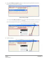
Page 41: ...lect System open the QuickPanel Setup tool and select the BatteryStatus tab Battery Life Prediction Example Note If the current time is not set on the device the QuickPanel Setup Tool dialog box will not be capable of provide an accurate battery life prediction To set the current time to display battery life prediction 1 If the current time is not set on the device the QuickPanel Setup Tool displa...

Page 42: ...s tab to display the correct battery life prediction information Example of Battery Life Prediction Displayed After Current Time Set 3 If the battery was replaced or removed on the QuickPanel QuickPanel Setup Tool BatteryStatusdisplays two possible scenarios related to the battery The battery life prediction is estimated based on this selection Battery Status Options ...

Page 43: ... device Battery is Not Present Message 5 If the option The battery was replaced is selected enter the date of when the battery was first used in a QuickPanel device This date should reflect the date of first use in any QuickPanel device not just the current device Select the date from the calendar and click Next 6 Enter the current date Select the current date and from the calendar and click Apply...

Page 44: ...e QuickPanel Operator Interface User Manual 7 Close and re open the QuickPanel Setup Tool dialog box to display the battery life prediction information Close and Reopen Message Battery Life Prediction Example after Battery Replacement ...

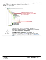
Page 45: ...ues HMI Tags Alarms System Info QuickPanel Device SNMP Manager QuickPanel ManagementInformation Base MIB Overview The QuickPanel SNMP Agent maintains a MIB that describes the managed device parameters like HMI Tags alarms and such The SNMP Manager uses the MIB to request specific information for the SNMP Agent and translates the information as needed for the SNMP Managers or Network Management Sys...

Page 46: ...e 1 3 6 1 4 1 24893 OID for qppMIB node 1 3 6 1 4 1 24893 1 5 2 1 1 It is highly recommended that you pre load GE MIBs GEIP SMI txt and GEIP PRODUCTS MIB txt in sequence prior to loading the QuickPanelMIB mib file into SNMP Managers to avoid any MIB compiler errors Attention Contact technical support or download the MIBs GEIP SMI txt and GEIP PRODUCTS MIB txt from the Support Site and QuickPanelMI...

Page 47: ...plays the HMI Alarms notification TRAP information with alarm objects as part of the Alarm Record The SNMP Manager is notified with the TRAP information when alarms are generated on the HMI running on a QuickPanel device OID for Alarm Trap 1 3 6 1 4 1 24893 1 5 2 1 1 10 ...

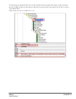
Page 48: ...the HMI running on a QuickPanel device Note The list of all HMI tags are populated within the hmiTags node of MIB tree and the HMI Tag access level is currently restricted to Read only for the SNMP Manager OID for starting HMI Tag element also called Index element 1 3 6 1 4 1 24893 1 5 2 1 1 50 1 1 If there are 40 HMI tags in total the last OID would be 1 3 6 1 4 1 24893 1 5 2 1 1 50 1 40 ...

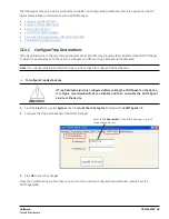
Page 49: ...ent The user can configure two different Trap Destinations IPAddresses Note If you do not want to be notified of Traps you do not need to configure Trap Destinations To configure Trap Destinations Attention If Trap Destination s is are configured after enabling the SNMP Agent on the device it is highly recommended that you disable and then re enable the SNMP Agent service on the device 1 From the ...

Page 50: ...formation Base MIB QuickPanelMIB mib file to a SD Card Attention It is highly recommended that you pre load GE MIBs GEIP SMI txt and GEIP PRODUCTS MIB txt in sequence prior to loading the QuickPanelMIB mib file into SNMP Managers to avoid any MIB compiler errors Contact technical support or download the MIBs GEIP SMI txt and GEIP PRODUCTS MIB txt from the Support Site and QuickPanelMIB mib can be ...

Page 51: ...a SD Card archive the QuickPanel MIB file to a folder on a machine running with SNMP Manager To load the MIB into the SNMP Manager from the SNMP Manager tool File menu select Load the MIBs Loading MIBs in 3rd Party SNMP Manager Tool If there are no errors the MIB will be loaded successfully and the SNMP Manager will be ready for communication with QuickPanel device operating as a SNMP Agent ...

Page 52: ...Var data type as R100 INT This maps LREALVar to DISPLAYSTRING in the MIB file 3 14 6 Establish SNMP Communication Attention SNMP communication requires that both the QuickPanel device and the SNMP Manager running on a machine are connected on a valid Ethernet network To establish SNMP communicationwith the QuickPanel device 1 Download the Project to the network connected QuickPanel device and star...

Page 53: ...o as a screensaver The configuration for this can be done at the ScreenSaver Tab in the QuickPanel Setup Tool window The dialog provides the following options 1 Enabiling Disabling the ScreenSaver 2 Browsing the video file to be run as the ScreenSaver 3 The elapse idle time setting to trigger the ScreenSaver ...

Page 54: ...54 GFK 2847W For public disclosure QuickPanel Operator Interface User Manual Notes ...

Page 55: ...ponsibility to register a claim with the carrier for damage incurred during shipment Note For phone numbers and email addresses refer to the section Contact Information After unpacking the unit record all serial numbers These are needed to contact Customer Care during the warranty period Save all shipping containers and packing material for future transport or shipping Verify that all system compo...

Page 56: ...terface User Manual QuickPanel Operator Interface Battery Qty 1 pre installed Serial Port Connector Qty 1 Power Connector Qty 1 Mounting Brackets Qty 4 Protective Sheet Qty 1 not shown Gasket Qty 1 not shown pre installed IC755CxWxxCDxExample Package Contents ...

Page 57: ...onfigure optional input devices communications ports and expansion adapters Warning To avoid personal injury or damage to equipment ensure that the dc supply is disconnected from power and the leads are not energized before attaching them to the unit s power supply plug Warning If this equipment is used in a manner not specified by the manufacturer equipment protection may be impaired Optional Eth...

Page 58: ...al 4 3 1 Connecting Input Power To connect input power 1 Verify that the power cable is not energized 2 Loosen the screw clamps on the mating power connector 3 Strip the insulation from the power cables 4 Secure the power cable to the mating connector noting polarity and tighten the screw clamps The torque for the attaching screws is 0 3 Nm 2 66 in lb 5 Apply dc power to the unit During normal sta...

Page 59: ...ding Proficy Historian require a unique Device Name Attention It is recommended to set a unique Device Name for the QuickPanel to avoid future conflicts 4 From the Control Panel double tap Network and Dial up Connectionsto configure network settings 5 Run the Backup Utility to save the settings 4 4 Runtime Setup To download an application to a QuickPanel Operator Interface set up a data link betwe...

Page 60: ...iated with a power failure or other unplanned shutdown of the QuickPanel unit In general programs are retained in flash memory and user data can be retained in BBSRAM Some operating system settings are retained only with user intervention Perform the following procedure to properly shut down the QuickPanel unit To shut down the QuickPanel unit 1 Quit any programs that are running and wait for all ...

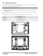
Page 61: ...g Battery Installation and Replacement Connectors 5 1 Protective Sheet Installation To install the protective sheet 1 Remove the protective film from the QuickPanel display screen 2 Wipe the display unit of any dust or fingerprints 3 Peel back a corner of the clear side of the protective sheet 4 Begin applying the corner to the display screen 5 Slowly apply the rest of the protective sheet smoothi...

Page 62: ...g the QuickPanel Operator Interface make sure the mounting area allows room to insert and remove the SD card cables and mounting brackets Select a location that allows natural convection air flow from bottom to top of the QuickPanel enclosure Do not mount the QuickPanel at an angle more than 30 from the vertical as illustrated in the following figure Mounting Angle ...

Page 63: ...ckPanel in an enclosure you will need the following equipment One 2 Phillips head screwdriver Mounting brackets supplied The mounting holes for IC755CxS06RDx IC755CxW07CDx and IC755CxS10CDx are located on the top and bottom sides of the unit IC755CxS06RDxMounting Holes IC755CxW07CDxMounting Holes ...

Page 64: ...public disclosure QuickPanel Operator Interface User Manual IC755CxS10CDxMounting Holes The IC755CxS12CDx and IC755CxS15CDx mounting holes are located on the top bottom and sides of the unit IC755CxS12CDxMounting Holes ...

Page 65: ...Mounting and Installation For public disclosure GFK 2847W 65 IC755CxS15CDxMounting Holes ...

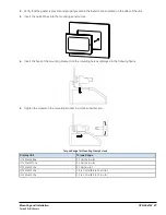
Page 66: ... insertions or removals of the unit and retightening of the mounting clips For full protection always use a fresh gasket The unit will not fit through the cutout with any cables connected or with the power supply plug inserted in the socket Caution When installing the QuickPanel into the panel pay careful attention while handling the unit so it does not drop and damage the unit To install the Quic...

Page 67: ...ut 4 Insert the hook of the mounting bracket into the mounting hole as displayed in the following figure 5 Tighten the screws on the mounting bracket in a clock wise direction Torque Range for Mounting Clamp Screws Display Unit Torque Range IC755CxS06RDx 0 3 Nm 2 66 in lb IC755CxW07CDx 0 3 Nm 2 66 in lb IC755CxS10CDx 0 7 Nm 6 in lb IC755CxS12CDx 1 0 to 1 2 Nm 8 9 to 10 6 in lb IC755CxS15CDx 1 0 to...

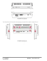
Page 68: ...e the mounting holes located on the back of the unit displayed in the following figures The mounting holes for IC755CxS06RDx and IC755CxW07CDx attach with M4 screws that are 6 mm 0 24 in or less in length The mounting holes for IC755CxSxxCDx attach with M4 screws that are 8 mm 0 32 in or less in length Torque Range for Mounting M4 Screws Display Unit Torque Range IC755CxS06RDx 0 7 to 0 8 Nm 6 2 to...

Page 69: ...e battery should only be performed by trained personnel and in a non hazardous location 2 If the QuickPanel Operator Interface is VESA mounted detach from the VESA arm when replacing the battery 3 The battery should only be replaced when the unit is powered off Caution 4 Care should be taken to protect and insert the battery with correct polarity 5 Do not use any metallic item to remove the batter...

Page 70: ... the IC755CxS06RDx only with GE battery part number IC755ACCBATT 1 Remove the battery cover by pressing down while sliding outward IC755CxS06RDxBattery Cover Removal 2 Connect the battery harness connector to the header noting keyed orientation Battery Part Number IC755ACCBATT IC755CxS06RDxBattery Harness Connection 3 Verify that the positive red is down and negative black is up ...

Page 71: ...ure GFK 2847W 71 4 Wrap the harness connector around to match the following figure Do not let the harness connector go above the tab Harness ConnectorOrientation 5 Slide the battery cover into place taking care not to pinch the harness connector ...

Page 72: ... IC755CxW07CDx only with GE battery part number IC755ACCBATT 1 Remove the battery cover by pressing down while sliding outward IC755CxW07CDxBattery Cover Removal 2 Connect the battery harness connector to the header noting keyed orientation Battery Part Number IC755ACCBATT Battery Harness Connection 3 Verify that the positive red connection is down and the negative black connection is up ...

Page 73: ...ure GFK 2847W 73 4 Wrap the harness connector around to match the following figure Do not let the harness connector go above the tab Harness ConnectorOrientation 5 Slide the battery cover into place taking care not to pinch the harness connector ...

Page 74: ...for the IC755CxSxxCDx Caution Replace the battery for the IC755CxSxxCDx only with GE battery part number IC755ACCBATTNL 1 Remove the screws quantity 7 from the back cover IC755CxSxxCDxScrew Locations Back Cover 2 Gently press on either side tab to release the back cover 3 Lift up and remove the back cover Side Tab for Cover Release ...

Page 75: ...attery will be exposed on the back of the unit Battery Part Number IC755ACCBATTNL IC755CxSxxCDxBattery 4 Gently remove the coin battery and replace with a new one noting the polarity of the battery 5 Replace the battery cover and tighten all screws to 0 5 Nm 4 4 in lb ...

Page 76: ...te Refer to the section Ethernet Port LED Operation The QuickPanel display is equipped with 10Base T 100 Base TXEthernet port s Connect an Ethernet network cable unshielded twisted pair CAT 5 to the unit through the RJ 45 connector s on the bottom of the enclosure LED indicators on the port indicate channel status The port can be accessed by Windows Embedded Compact 7 network communications or by ...

Page 77: ...ns an IP address during QuickPanel initialization There must be a DHCP server on the connected network for a valid IP address to be assigned Contact your network administrator to ensure correct DHCP server configuration Manual Method Specify the numeric addresses obtained from your network administrator for the QuickPanel IPAddress Subnet Mask and Default Gateway if applicable Note Run the Backup ...

Page 78: ...res At a minimum the cable must be rated for 75 C 167 F or more Secure the serial cable to the mating connector while noting signal orientation and tighten the screw clamps The torque for the attaching screws is 0 3 Nm 2 66 in lb Connectors Euro Terminal Tyco Electronics 284539 5 Mating Connectors Tyco Electronics 284510 5 Serial Port COM1 Details Interface RS 232 COM1 Pin Details Pin Signal Name ...

Page 79: ...able must be rated for 75 C 167 F or more Secure the serial cable to the mating connector while noting signal orientation and tighten the screw clamps The torque for the attaching screws is 0 3 Nm 2 66 in lb Serial Port COM1 Details Interface x1 RS 232 Connectors Euro Terminal Tyco Electronics 284539 5 Mating Connector Tyco Electronics 284510 5 COM1 Pin Details Pin Signal Name 1 TXD 2 RXD 3 RTS 4 ...

Page 80: ...e following guidelines Terminal blocks are supplied The mating terminal blocks support stranded 30 to 14 AWG 0 05 to 2 00 mm2 wires At a minimum the cable must be rated for 75 C 167 F or more Secure the serial cable to the mating connector while noting signal orientation and tighten the screw clamps The torque for the attaching screws is 0 3 Nm 2 66 in lb Connectors Euro Terminal Tyco Electronics ...

Page 81: ...ON 7 OFF 8 ON SW3 1 ON 2 OFF 3 OFF 4 OFF Serial Port COM2 Details Interface RS 232C 485 default is RS 485 Half duplex COM2 Pin Details Pin RS 232C RS 485 Signal Name Signal Name Full duplex Signal Name Half duplex 1 TXD TXD DATA 2 RXD TXD DATA 3 RTS RXD DATA 4 CTS RXD DATA 5 SGND SG SG Full duplexRS 485 is backwards compatibleto RS 422 mode Pins 1 3 and 2 4 are connected internally COM1 COM2 Pin 1...

Page 82: ...SW4 1 ON 2 ON 3 OFF 4 OFF 5 ON 6 ON 7 OFF 8 OFF SW5 1 OFF 2 OFF 3 OFF 4 OFF Example of Full duplex RS 422 Mode Connection COM2 DIP Switch Setting for RS 422 DIP SW Bit ON OFF SW2 1 OFF 2 OFF 3 OFF 4 OFF 5 ON 6 ON 7 OFF 8 ON SW3 1 OFF 2 ON 3 OFF 4 OFF Example of Half duplex RS 485 Mode Connection ...

Page 83: ...isclosure GFK 2847W 83 DIPSW Bit ON OFF SW4 1 ON 2 ON 3 ON 4 ON 5 ON 6 ON 7 OFF 8 OFF SW5 1 OFF 2 OFF 3 OFF 4 OFF COM2 DIP Switch Setting for RS 485 DIPSW Bit ON OFF SW2 1 OFF 2 OFF 3 ON 4 OFF 5 ON 6 ON 7 OFF 8 ON SW3 1 OFF 2 ON 3 OFF 4 ON ...

Page 84: ...d with the QuickPanel is for optional keyboard or mouse support other devices require installation of the custom driver software Interface USB 2 0 Number of Ports Two Connectors Type A connector Maximum Supply Current 0 5 A per port Pin Signal Name Pin out 1 USB_VCC 2 USB_D 3 USB_D 4 USB_GND 5 7 4 2 USB Device Port Details for IC755CxS06RDx IC755CxW07CDx and IC755CxSxxCDx The USB device port allow...

Page 85: ...USB connection sequence on the device and need to be configured accordingly 5 7 4 4 Wi Fi Support for All Models Using Adapters Recommended USB wifi adapters based on the Ralink chipset are as follows RT 2070 RT 2870 RT 3070 RT 3071 RT 3072 5 7 5 Audio LINE OUT Details for IC755CxS06RDx IC755CxW07CDx and IC755CxSxxCDx Interface LINE OUT stereo Number of Ports One Connectors φ3 5 mm jack Maximum ou...

Page 86: ...d The SD card slot is spring loaded for easy insertion and removal Note Micro SD slot is not supported on the 6 display unit IC755CxS06RDx Connectors SD card slot push in push out method Card support SD SDHC memory card Maximum capacity 32 GB Note During insertion observe the orientation of the SD card as displayed in the following figures IC755CxS06RDxSD Card Location IC755CxW07CDxSD Card Locatio...

Page 87: ...Mounting and Installation For public disclosure GFK 2847W 87 IC755CxSxxCDxSD Card Location ...

Page 88: ...88 GFK 2847W For public disclosure QuickPanel Operator Interface User Manual Notes ...

Page 89: ...he protective sheet do not operate the touchscreen with any hard materials such as a screwdriver This could damage the touchscreen display Note IC755CxS06RDx 6 display is an Analog Resistive touch display that does not support two point touch capability Single point gestures such as swipe pan and double tap are supported 6 1 1 Display BrightnessAdjustment To adjust the brightness of the display 1 ...

Page 90: ...kPanel Setup Tool and select the Backlight tab to display the Backlight Display Properties window 2 Set the backlight to automatically turn off in a specific amount of time Select Automatically turn off the backlight From the drop down menu select a time between 15 sec to 2 hr 3 Tap OK to exit the QuickPanel Setup Tool 4 Run the Backup Utility to save the settings ...

Page 91: ...pen the QuickPanel Setup tool 2 Select the TouchPanel tab 3 Select Recalibrate Touch Screen 4 Select Recalibrate Touch Sensor Note During IC755CxS06RDx or IC755CxW07CDx touchscreen sensor re calibration the user is prompted to activate a switch located in the battery compartment This is not applicable to any other display units 5 Remove the battery cover and press the switch Switch Battery Cover 6...

Page 92: ...o configuration is required To use an external keyboard connect the keyboard to the unit using the USB cable 6 2 2 Soft Input Panel The Soft Input Panel SIP is a touchscreen keyboard that may be used in place of a standard hardware keyboard An icon in the system tray enables the user to view or hide the SIP To show or hide the SIP from the system tray located on the task bar tap the icon and selec...

Page 93: ...er general printing options For the fastest printing performance select draft mode and portrait orientation and disable color for print settings These settings also minimize the amount of memory needed to print a document The built in driver has a document spooling function to improve GUI performance This spooler supports only one document at a time However on an Ethernet connected printer the pri...

Page 94: ... split between program memory and storage memory can be adjusted as necessary to make more room for one or the other depending on specific application needs For example if an application is short of memory alter the DRAM memory allocation from the System Properties window Setting the Program Memory too low may prevent additional applications from starting or may cause currently running application...

Page 95: ...e amount of memory allocated to and used by each area is displayed in the window The blue slider bar indicates the current amount of unallocated SDRAM and determines the boundaries within which the slider can move System Memory Slider Bar Note Storage memory is limited to a maximum of 128 MB Using the slider bar to increase storage memory will provide more RAM based storage in the folder Object St...

Page 96: ...96 GFK 2847W For public disclosure QuickPanel Operator Interface User Manual Notes ...

Page 97: ...It is recommended to have a Network Architect on site and working with Secomea team to enable this functionality To access the Secomea Configurationtool and enable the QuickPanel on the Secomea network 1 From the QuickPanel Start menu select Programs to display the Secomea Configuration tool window 2 Enable the QuickPanel device on the Secomea network Select Enable Remote Management and enter the ...

Page 98: ...ar functionality for mobile devices GateManageris the central component of Secomea s Industry solution The GateManager M2M Server operates as a termination point for all LinkManagers and SiteManagers All connections and the encrypted traffic between LinkManagers and devices controlled by SiteManagers are handled by the GateManager where all events are also logged Note The GateManager is typically ...

Page 99: ...For public disclosure GFK 2847W 99 Secomea Products used with QuickPanel in Application ...

Page 100: ...ings and 2 Registry Settings Tab This tab has the different names of different settings that the user can select to save the settings value to the file Note 1 The settings tab of Save and Restore Settings dialog is not used for setting the values for any device parameters It is only used to make selection of the parameter settings that the user wants wishes to a file 2 The feature supports saving ...

Page 101: ...lue to a registry key the click on the Add button this displays dialog to enter the values for Key Path Name Type and value After entering the values click the OK button to close the dialog and the entered data can be seen as a record in the Registry tab ...

Page 102: ... the edit button to open the dialog box that shall allow you to edit the data Import registry data from XML file An alternate method to input the data to the registry is by using the Import option where the registry value data is put in a XML file and the imported using the import option in the dialog The schema of the XML data can be seen in the screenshot below ...

Page 103: ... The feature does not support editing any registry keys inside HKEY_CLASSES_ROOT Save the Settings to a file To save the settings and registry values to a file click on the Save button This displays the file save dialog to select the folder location and provide the file name Click the OK button to complete the creation and saving of data to the file ...

Page 104: ...e the settings from a file to a QP following steps need to be executed 1 Make sure that the file is browsable from the target QP 2 Click on the Restore button select Yes when prompted for confirmation 3 In the Open File dialog browse and select the qps file from which you would like to restore the data and click on OK button ...

Page 105: ...For public disclosure GFK 2847W 105 ...

Page 106: ...ure QuickPanel Operator Interface User Manual Enhance Security enabled QP box shall prompt for Enhance Security password on clicking the Save or Restore button Only on successful authentication the corresponding operation is executed ...

Page 107: ...sion 2 applicable only to 6 Display unit Certification by Underwriter sLaboratories to UL 61010 1 UL61010 2 201 CSA C22 2 No 142 M1987 CSA 61010 1 CSA 61010 2 201 ISA 12 12 01 standard and CSA C22 2 No 213 M1987 Explosive AtmospheresDirective European Safety for Hazardous Areas Equipment Group II Category 3 Gas Groups IIC Dust Group IIIC Certification in accordance with the ATEX Directive 14 34 EU...

Page 108: ... units 1 The equipment shall only be used in an area of at least pollution degree 2 as defined in IEC 60664 1 Note Pollution degree 2 can be achieved when the installation is in a controlled environment with suitably controlled condensation or airborne pollution 2 The equipment shall be installed in an enclosure that provides a minimum ingress protection of IP 54 in accordance with IEC 60079 0 3 T...

Page 109: ...ing clamp by pushing the lever of the retaining clamp Then close the retaining clamp to fit the cable size USB retaining clamp for IC755CSW07CDACAmust be used in hazardous location installations as follows 1 Connect the USB retaining clamp plate 2 Connect the USB cable and insert the retaining clamp into the retaining clamp plate ...

Page 110: ...hed according to FCC guidelines Note This equipment has been tested and found to comply with the limits for a Class A digital device pursuant to Part 15 of the FCC Rules These limits are designed to provide reasonable protection against harmful interference when the equipment is operated in a commercial environment This equipment generates uses and can radiate radio frequency energy and if not ins...

Page 111: ...ements the following installation and operation considerations were taken into account Shielding USB cables Limiting RS 232 cables to 15 m 49 2 ft in length Using Audio ports only during operational maintenance Although these considerations were deliberated during testing actual EMC environments vary greatly Therefore these considerations may not be necessary Likewise additional measures such as f...

Page 112: ...GFK 2847W For public disclosure QuickPanel Operator Interface User Manual Notes ...

Page 113: ...k IC755CSS10CDx QuickPanel 10 Color TFTwith Multi touchProjected Capacitive Screen 12 24 V dc Powered IC755ACC10GAS QuickPanel 10 ReplacementGasket IC755ACC10MNT QuickPanel 10 Accessory Kit Replacement Mounting Clips Power and Serial Port Connectors IC755ACC10PRO QuickPanel 10 ReplacementScreen Protectors Qty 3 IC755CSS10CDACA QuickPanel 10 with Conformal Coating IC755CSS12CDx QuickPanel 12 Color ...

Page 114: ...GFK 2847W For public disclosure QuickPanel Operator Interface User Manual Notes ...

Page 115: ...Appendix B Orderable Part Numbers For public disclosure GFK 2847W ...

Page 116: ......

Page 117: ... cable to the mating connector while noting signal orientation and tighten the screw clamps The torque for the attaching screws is 0 3 Nm 2 66 in lb Interface x1 RS 232 x1 RS 232 485 default is RS 485 Connectors Euro Terminal Tyco Electronics 1 284539 0 Mating Connector Tyco Electronics 1 284510 0 Pin Signal Name Pin out COM1 5 4 3 2 1 5 4 3 2 1 1 TXD 2 RXD 3 RTS 4 CTS 5 SGND COM2 RS 232 485 1 TXD...

Page 118: ...Automation Controls 1 800 433 2682 1 434 978 5100 www geautomation com GFK 2847W For public disclosure ...

Reviews: