background image

15

Troubleshooting tips…

www.GEAppliances.com

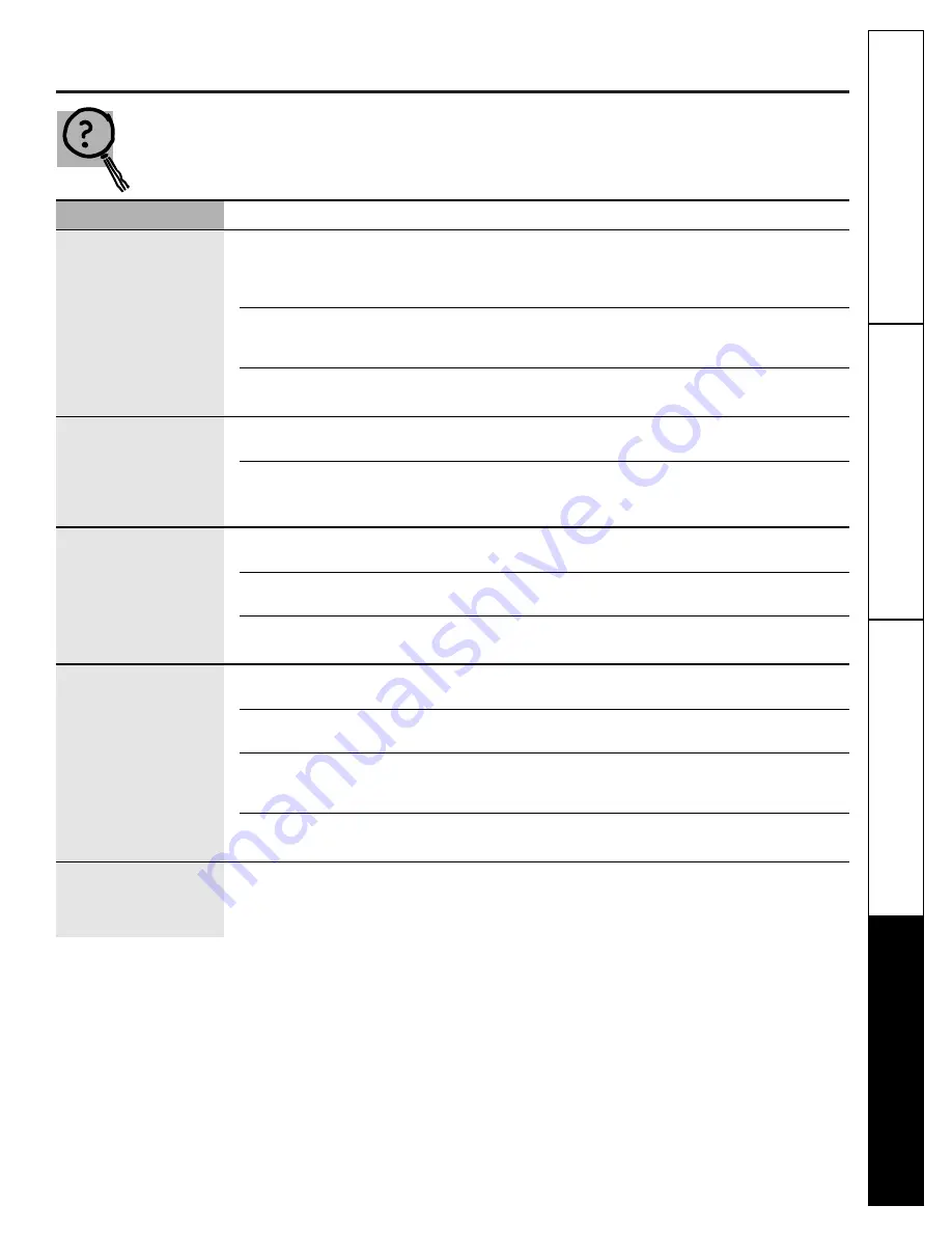
Save time and money! Review the chart on this page first
and you may not need to call for service.

Problem

Possible Causes

What To Do

No display/faint display

Supply voltage not correct.

Using a voltmeter, check the supply voltage to the 

thermostat. Voltage operating range for the thermostat 

is 18-30 VAC/VDC. If measured voltage is out of this 

range, troubleshoot the supply voltage to the unit.

Thermostat is damaged.

Replace with a new thermostat. Check the supply voltage 

to the unit before connecting second thermostat (see 

above).

Power wiring to unit is incorrect.

Refer to Figures 1 & 2 in the 

Installation Instructions

for 

correct wiring.

Keypad buttons do 

No power to the unit.

Make sure the display is working correctly. If not, 

not work.

follow step one above.

Thermostat is damaged.

Replace with a new thermostat. Check the supply 

voltage to the unit before connecting second 

thermostat (see above).

Thermostat will not

Thermostat setpoint is satisfied.

Raise the temperature setpoint more than 2° above

call for heat.

current temperature.

Unit wiring is incorrect.

Refer to Figures 1 & 2 in the 

Installation Instructions 

for 

correct wiring.

Unit is ‘OFF.’

Make sure the 

FLAME

icon is displayed and blinking. 

If not, push the 

MODE

button until it is displayed.

Thermostat will not

Thermostat setpoint is satisfied.

Lower the temperature setpoint more than 2°

call for cooling.

below current temperature.

Unit wiring is incorrect.

Refer to Figures 1 & 2 in the 

Installation Instructions 

for 

correct wiring.

Unit is ‘OFF.’

Make sure the 

SNOWFLAKE

icon is displayed and 

blinking. If not, push the 

MODE

button until it 

is displayed.

Short cycle delay still active.

Wait 4 minutes. The unit’s short cycle timer is in 

operation.

Fan does not turn on 

Fan failure.

Place a jumper between the R and G terminals.  

with the system.

The fan should come on. If it does, replace the 

thermostat.

Troubleshooting T

ips

Operating Instructions

Safety Instructions

Installation Instructions

Summary of Contents for RAK147P1

Page 1: ...ing Setpoint Temperature 5 Selecting Temperature Scale 4 Thermostat Overview 2 3 Time Format 5 Verification 10 Installation Instructions Location 11 Mounting and Wiring 11 13 Specifications 14 Tools Required 11 Troubleshooting Tips 15 Customer Service Warranty 20 Write the model and serial numbers here You can find them on a label on the thermostat RAK147P1 RAK163P1 Owner s Manual Installation Ins...

Page 2: ...l Automatically changes from heating to cooling Thermostat Overview Figure 1 RAK163P1 and RAK147P1 Display LCD SEGMENT DESCRIPTION Day indicator Indicates the day of week AM PM indicator Indicates AM or PM Time display Displays time program time or set temperature Program indicator Indicates the operating or editing program Morning Day Evening and Night flashes when temporary hold Hold indicator I...

Page 3: ...n mode of the FAN between AUTO ON RESET Hardware resets signal to reset the thermostat Keyboard Functions Initial Power Up The thermostat will reset after power up or if the reset button is pressed During reset all LCD segments and the LCD backlight will be turned on After one second and when all keys are released the thermostat will start At the same time the memory and I O ports of the MCU will ...

Page 4: ...e is selected the C indicator will be displayed The current operating program is DAY If the indicator is flashing temporary hold is active Icon explanation If heating is selected FLAME icon will be displayed If a call for heating is made FLAME icon will be flashing If cooling is selected SNOWFLAKE icon will be displayed If a call for cooling is made SNOWFLAKE icon will be flashing If Auto changeov...

Page 5: ...etpoint temperature and SET TEMP indicator will be displayed The HEAT COOL or AUTO indicator will turn on indicating the current operating system Figure 7 Temperature Setpoint Example To change the setpoint temperature press and hold either or for more than 1 second The entire display will flash once and the setpoint temperature can be changed Continue to hold the key or release and press again to...

Page 6: ...rary override Figure 10 HOLD Display Day Time Setting Mode In NORMAL mode press DAY TIME to enter the DAY TIME SETTING mode The LCD will be cleared except for the time and day of week indicator When the hour is flashing press increase setting or decrease setting to adjust hour Press DAY TIME again Minutes will be flashing Press or to adjust minutes Press DAY TIME again The day will be flashing Pre...

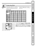
Page 7: ... p m 11 p m Wednesday 6 a m 8 a m 5 p m 11 p m Thursday 6 a m 8 a m 5 p m 11 p m Friday 6 a m 8 a m 5 p m 11 p m Saturday 6 a m 8 a m 5 p m 11 p m Sunday 6 a m 8 a m 5 p m 11 p m Default Program To review or change the program press PROGRAM in NORMAL mode The time period MORNING of the Weekday Program will be displayed first The system icon in Figure 12 indicates it is in the heating program If th...

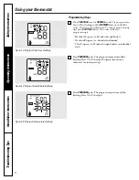
Page 8: ...e Saturday and Sunday 7 Day Program i e Monday through Sunday on individual days Programming Steps Figure 13 Program Time Hour Flashing Press PROGRAM again The program time minute will be flashing Press or to adjust Program time minute advances 10 minutes per step Figure 14 Program Time Minute Flashing Press PROGRAM again The program temperature will be flashing Press or to adjust Figure 15 Progra...

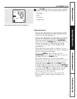
Page 9: ...amming are required follow steps 1 5 for the individual 7 day programming When adjusting the program time or temperature press and hold or for 2 seconds for fast advance During fast advance the data will stop flashing To return to NORMAL mode at any time press the HOLD RETURN button or wait 5 seconds with no action and the display will return to NORMAL mode The setpoint temperature cannot be set b...

Page 10: ...ct the heat or cool system Press the or to adjust the setpoint temperature above or below the current ambient temperature The thermostat should call for either heating or cooling and the fan should turn on Press the FAN button to change from FAN AUTO to FAN ON The fan should come on automatically If the thermostat does not operate correctly proceed to the Troubleshooting section Auto Changeover Th...

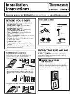
Page 11: ...rence Skill level Installation of this appliance requires basic mechanical skills Completion time 1 hour Proper installation is the responsibility of the installer Product failure due to improper installation is not covered under the Warranty On an interior wall since the temperature of an exterior wall varies with outdoor conditions approximately 5 ft 1 5 m above the floor THERMOSTAT LOCATION If ...

Page 12: ...des as they apply CONNECT WIRES 4 To re install the thermostat to the base attach the tabs on the bottom of the thermostat front to the small slots on the base bottom and push up until they snap in place RE INSTALL THERMOSTAT TO BASE 5 Feed the thermostat control wires through the rectangular opening in the base and using the base as a template mark the location of the two vertical mounting holes ...

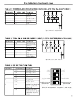
Page 13: ...ERMINAL NO TERMINAL NAME FUNCTION 1 W Heating 2 C Common 3 R 24 VAC or VDC 4 Y Cooling 5 G Fan TABLE 1 TERMINALS FOR FIVE WIRES HEAT COOL SYSTEM RAK163P1 ONLY Figure 1 RAK163P1 5 Wire Connection TABLE 2 TERMINALS FOR SIX WIRES 2 HEAT 1 COOL SYSTEM RAK147P1 ONLY Figure 2 RAK147P1 6 Wire Connection TERMINAL NO TERMINAL NAME FUNCTION 1 W Auxiliary Heating 2 C Common 3 R 24 VAC or VDC 4 Y Cooling 5 G ...

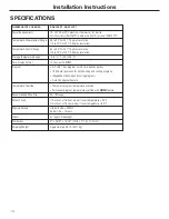
Page 14: ... and 7 day program with 4 time periods per day 10 Minute resolution for both heating and cooling programs Independent heating and cooling programs Auto Changeover Feature Temperature Override Temporary program temperature override Permanent program temperature override with HOLD feature Recommended Wire Size 24 18 Gauge Safety Circuit 1 Auto cut off in heat mode if room temperature 90 F 2 Auto cut...

Page 15: ...unit before connecting second thermostat see above Thermostat will not Thermostat setpoint is satisfied Raise the temperature setpoint more than 2 above call for heat current temperature Unit wiring is incorrect Refer to Figures 1 2 in the Installation Instructions for correct wiring Unit is OFF Make sure the FLAME icon is displayed and blinking If not push the MODE button until it is displayed Th...

Page 16: ...16 Notes Troubleshooting Tips Operating Instructions Safety Instructions Installation Instructions ...

Page 17: ... I m p o r t a n t M a i l T o d a y General Electric Company Louisville Kentucky www GEAppliances com First Name Mr Ms Mrs Miss Street Address City State Date Placed In Use Month Day Year Zip Code Apt Last Name Phone Number _ _ Model Number Serial Number E mail Address Occasionally we may allow selected companies to send you information Check here if you do not want this information ...

Page 18: ...18 Troubleshooting Tips Operating Instructions Safety Instructions Installation Instructions Notes ...

Page 19: ...19 Notes Troubleshooting Tips Operating Instructions Safety Instructions Installation Instructions ...

Page 20: ... resetting of circuit breakers Damage to the product caused by improper power supply voltage accident fire floods or acts of God Incidental or consequential damage caused by possible defects with this thermostat What GE Will Not Cover This warranty is extended to the original purchaser and any succeeding owner for products purchased for home use within the USA In Alaska the warranty excludes the c...

Reviews: