background image

18

31-5000842   Rev. 0

FCC STATEMENT

NOTE:

 This equipment has been tested and found to comply 

with the limits for a Class B digital device, pursuant to part 
15 of the FCC Rules. These limits are designed to provide 
reasonable protection against harmful interference in a 
residential installation. This equipment generates, uses and 
can radiate radio frequency energy and, if not installed and 
used in accordance with the instructions, may cause harmful 
interference to radio communications. However, there is 
no guarantee that interference will not occur in a particular 
installation. If this equipment does cause harmful interference 
to radio or television reception, which can be determined by 
turning the equipment off and on, the user is encouraged to 
try to correct the interference by one or more of the following 
measures:

•  Reorient or relocate the receiving antenna
•  Increase the separation between the equipment and 

receiver

•  Connect the equipment into an outlet on a circuit different 

from that to which the receiver is connected

•  Consult the dealer or an experienced radio/TV technician 

for help

CAN ICES-003 (B) / NMB-003 (B)

Summary of Contents for RAK190V

Page 1: ...TION INSTRUCTIONS WIRING 5 INSTALLER MENU 10 USING THE THERMOSTAT OVERVIEW 14 TROUBLESHOOTING 15 RESETTING 15 WARRANTY 17 FCC STATEMENT 18 THERMOSTAT Energy Management INSTALLATION INSTRUCTIONS RAK190...

Page 2: ...Operating Ambient 40 F to 99 F 4 C to 37 C Occupancy Sensor Range 5 meters 109 6 degrees x 109 6 degrees Field of View O1 O2 Dry Contact Ratings 5A 32VAC or 5A 30VDC Humidity Range Accuracy 0 to 95 o...

Page 3: ...oving the existing thermostat Failure to do so could result in risk of electric shock INSTALLATION INSTRUCTIONS TO REMOVE EXISTING THERMOSTAT 1 Turn off power to heating and cooling system by removing...

Page 4: ...ostat away from working area 6 8VLQJ D GULOO ELW GULOO KROHV LQ WKH ORFDWLRQV RX KDYH PDUNHG IRU mounting 7 Use a hammer to tap supplied anchors in mounting holes 8 Align thermostat base with mounting...

Page 5: ...ordinances This control is a precision instrument and should be handled carefully Rough handing or distorting components could cause the control to malfunction To prevent electrical shock and or equip...

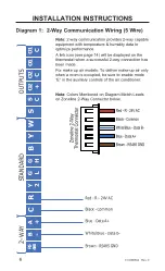
Page 6: ...2 way communication provides 2 way capable equipment with temperature humidity data to optimize performance A link icon see page 14 will be displayed on the thermostat when a successful 2 way connecti...

Page 7: ...IONS RS 485 B A C R Y 2 G L G H B Y W S S C O2 O2 C O1 O1 C 2 WAY STANDARD OUTPUTS Low Fan High Fan Reversing Valve Common 24V AC Compressor Aux Heat 2nd Stage Compressor Diagram 2 Standard Communicat...

Page 8: ...High Fan Reversing Valve Common 24V AC Compressor Aux Heat Op onal Occ Out INSTALLATION INSTRUCTIONS Diagram 3 Standard Communication Wiring 2 Heat 1 Cool Note With single stage compressor configurati...

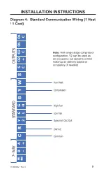
Page 9: ...an be used as an occupancy out signal to control make up air delivery based on occupancy if needed RS 485 B A C R Y 2 G L G H B Y W S S C O2 O2 C O1 O1 C 2 WAY STANDARD OUTPUTS Low Fan High Fan Common...

Page 10: ...shown on the display Once in the menu change setting selection Mode advances to next menu item Fan returns to previous menu item Power saves changes and exits Note After two minutes of no key presses...

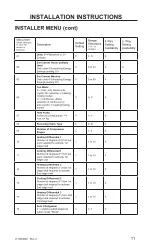
Page 11: ...cyclic in heating cooling modes C A C X 07 Heat Pump Is the unit a heat pump Y Yes n No Y Y n X 08 Reversing Valve Type b b O X 09 Number of Compressor Stages 2 1 2 X 10 Heating Differential 1 Number...

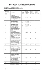
Page 12: ...eded this is an offset to calibrate room humidity reading 0 9 to 9 X X 21 Occupancy Energy savings OF No temperature setbacks are allowed Y Temperature setbacks are allowed when no occupancy is detect...

Page 13: ...ccupancy driven setbacks are permitted Note Only Available if Occupancy Energy Savings setting 21 is set to S 9 0 23 X X 30 Scheduled Energy Savings Stop Time military time If using Scheduled Energy S...

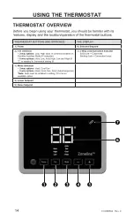
Page 14: ...nt 2 Fan Selection 2 way options Low High auto or continuous based on Zoneline Auxiliary Mode 1 selection 8 wire options Auto Low Auto High Low and High if C is enabled in thermostat setting 6 7 2 Way...

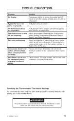
Page 15: ...High or Low in 8 wire mode fan will run continuously If thermostat is in 2 way control mode verify the Auxiliary settings of the Zoneline HVAC unit Compressor doesn t run or turn off immediately when...

Page 16: ...16 31 5000842 Rev 0 NOTES...

Page 17: ...This warranty is extended to the original purchaser and any succeeding owner for products purchased for use within the USA and Canada In Alaska the warranty excludes the cost of shipping or service ca...

Page 18: ...to radio communications However there is no guarantee that interference will not occur in a particular installation If this equipment does cause harmful interference to radio or television reception w...

Page 19: ...BLAGE 5 MENU DE L INSTALLATEUR 10 UTILISATION DU THERMOSTAT APER U DU THERMOSTAT 14 D PANNAGE 15 R INITIALISATION 15 GARANTIE 17 D CLARATION DE LA FCC 18 THERMOSTAT Gestion de l nergie INSTRUCTIONS D...

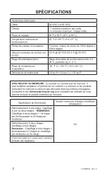
Page 20: ...9 F 4 37 C Port e du capteur d occupation 5 m tres champ de vision de 109 6 degr s x 109 6 degr s Valeurs nominales de contact sec O1 O2 0 5 A 32 VCA OU 5 A 30 VCC Plage d humidit pr cision Plage d hu...

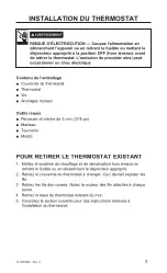
Page 21: ...ux Outils requis Perceuse et m che de 5 mm 3 16 po Marteau Tournevis 0DVWLF INSTALLATION DU THERMOSTAT POUR RETIRER LE THERMOSTAT EXISTANT 1 Mettez le syst me de chauffage et de climatisation hors ten...

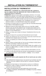
Page 22: ...thermostat du lieu de travail 6 Utilisez une m che de 5 mm 3 16 po pour percer des avant trous aux emplacements marqu s pour les vis bois 7 Utilisez un marteau pour rentrer les ancrages fournis dans...

Page 23: ...ment de pr cision et il doit tre manipul soigneusement Une manipulation brusque ou la d formation des composantes peut causer la d faillance du contr leur Pour pr venir les chocs lectriques et les dom...

Page 24: ...oies fournit un quipement 2 voies avec des donn es de temp rature et d humidit pour optimiser les performances Une ic ne de lien voir page 14 s affiche sur le thermostat lorsqu une connexion 2 voies a...

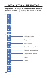
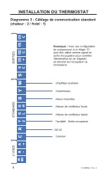
Page 25: ...on 24V AC Compressor Aux Heat 2nd Stage Compressor Diagramme 2 C blage de communication standard chaleur 3 froid 2 r glage par d faut en usine INSTALLATION DU THERMOSTAT 2 VOIES STANDARD SORTIES Chauf...

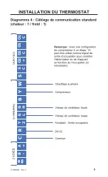
Page 26: ...ndard chaleur 2 froid 1 Remarque Avec une configuration de compresseur un tage Y2 peut tre utilis comme signal de sortie d occupation pour contr ler l alimentation en air d appoint en fonction de l oc...

Page 27: ...si n cessaire RS 485 B A C R Y 2 G L G H B Y W S S C O2 O2 C O1 O1 C 2 WAY STANDARD OUTPUTS Low Fan High Fan Common 24V AC Compressor Aux Heat Op onal Occ Out Diagramme 4 C blage de communication sta...

Page 28: ...ermet de modifier la s lection des param tres Mode Permet d acc der l l ment de menu suivant Fan Permet de revenir l l ment de menu pr c dent Power Permet d enregistrer les modifications et de quitter...

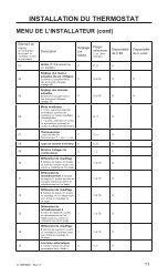
Page 29: ...C A C X 07 Thermopompe L unit est elle une thermopompe Y Oui n non Y Y n X 08 Type de robinet inverseur b b O X 09 Nombre d tages du compresseur 2 1 2 X 10 Diff rentiel de chauffage 1 Nombre de degr...

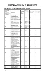
Page 30: ...21 conomies d nergie selon l occupation OF Aucune d viation de temp rature n est autoris e Y Les d viations de temp rature sont autoris es lorsque aucune occupation n est d tect e S conomies d nergie...

Page 31: ...nt si le param tre 21 conomies d nergie selon l occupation est r gl sur S 9 0 23 X X 30 Heure d arr t des conomies d nergie programm es heure militaire Si vous utilisez l option conomies d nergie prog...

Page 32: ...lection du mode auxiliaire no 1 du Zoneline fonctionnement automatique ou continu Options 8 fils Basse auto Haute auto Basse et Haute si C est activ au param tre 6 du thermostat 7 Indicateur de commu...

Page 33: ...ntilateur S il est r gl sur High ou Low en mode 8 fils le ventilateur fonctionne en continu Si le thermostat est en mode de contr le 2 voies v rifiez les r glages auxiliaires de l unit de climatisatio...

Page 34: ...16 31 5000842 Rev 0 REMARQUE...

Page 35: ...aire pour valider la garantie Cette garantie limit e est consentie son premier acheteur et tout propri taire subs quent pour les produits achet s pour utilisation aux tats Unis et au Canada En Alaska...

Page 36: ...aux communications radio Cependant il n y a aucune garantie qu un brouillage nuisible ne se produira pas dans une installation particuli re Si cet quipement cause un brouillage nuisible sur votre pos...

Reviews: