


FOR 5200 AND 5500 SERIES MODELS ONLY
(RAK4002B is also required)
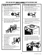
1.
Remove the room cabinet front from the unit.
2.
Measure 6
″
down the cord from where it emerges
from the back of the yellow 9-pin connector and cut
the cord through at this point.
3.
Carefully remove 3
″
of the cordset insulation so as to
expose the three insulated wires.
4.
Strip 3/4
″
of the
insulation away at the
end of each of the
three wires (L1,
Neutral, and Ground).
5.
Remove the 2 “A” screws (from the RAK4002B kit)
and remove the cover from the box.
6.
Use the round knockout at the bottom of the junction
box to attach conduit coming from the branch circuit.
Leave 6
″
of wire free at the end of the conduit to
allow connections to be made.
7.
Install the box to the unit with the “B” screw. Be sure
the tab and the box wall at the lower right rear corner
of the box straddle the barrier.
8.
Connect the branch
circuit conductors
to the stripped cord
leads with field-
supplied wire nuts.
9.
Plug the 9-pin
connector fully into
place in the unit,
mating with the
9-pin receptacle.
Be sure the locking
tabs at the top and bottom are engaged.
10.
Dress the wiring inside the junction box and attach
the cover plate with screws “A” and “C.”
11.
Reinstall the room cabinet front.
FOR 230/208 VOLT DIRECT CONNECT APPLICATIONS ONLY
3
3/4
″
3
″
Connector
6
″
Conduit
9-pin
connector
Unit 9-pin
receptacle
C
A
C
A
B
C
A
C
A
FOR 7500 SERIES MODELS ONLY
1.
Measure 7
″
down the cord from where it emerges
from the back of the yellow 9-pin connector and cut
the cord through at this point.
2.
Carefully remove 6
″
of the cordset insulation
so as to expose the three insulated wires.
3.
Strip 3/4
″
of the insulation away at the end of each
of the three wires (L1, L2, and Ground).
4.
Remove the unit front panel by removing the filter,
taking out the four front screws, the upper two
screws from the top of the panel, and the shipping
screws on each side, if present. (Discard the two side
shipping screws, if present.)
5.
Remove the junction box cover by taking out the
front two screws.
6.
Use the round knockout hole at the top of the
junction box to install conduit coming from the
branch circuit. Install and clamp the conduit through
the conduit clamp and bring wire leads into the
junction box. Leave 8
″
of wire free from the end of
the conduit.
3/4
″
6
″
Connector
7
″
Junction box
Junction box
cover
Conduit
Conduit
clamp
continued on next page
RAK4002B


