


GE Medical Systems
Information Technologies
Responder 1000/1100
Page 27
/
38
Service Instruction
───────────────────────────────────────────────────────────────────
227 487 20 Rev G
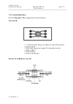
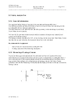
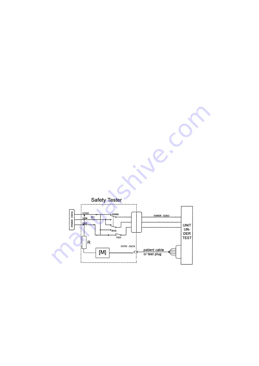
8.3.4 Patient Leakage Current
This test performs a leakage current test under single fault conditions (S.F.C.) dependent of
domestic power outlet with 115 or 230 V AC as source into the floating inputs.
The following signal have to be tested:
From paddles
In any case, the leakage current is measured from paddles of unit under test, to ground.
For testing the floating input from paddles, the test is measured on each defibrillator paddle.
Connect the unit under test to your Safety Tester.
-
Referring to the electrical diagram, measurements have to be done under following conditions
*
Polarity switch NORM and RVS
*
GND switch
GND closed
*
S1
closed
Test has failed if the measured values are greater than
100
μ
A
at defibrillator paddles.
Electrical Diagram for Patient Leakage Current Test
For protection of the person, the following values of resistor R may be used:
Type BF
22 kOhm (120 to 130 V)
47 kOhm (220 to 240 V)
Type CF
100 kOhm (220 to 240 V)
Summary of Contents for Responder 1000
Page 1: ...Responder 1000 1100 Version V 1 0 Servicing Instructions 227 487 20 ENG Revision G ...
Page 39: ......
Page 40: ......
Page 41: ......
Page 42: ......
Page 43: ......
Page 44: ......
Page 45: ......
Page 53: ......
Page 54: ......
Page 56: ......
Page 57: ......
Page 58: ......
Page 59: ......


