SECTION 4: Repair
2025653-048 Revision B
Responder
™
2000
Page 33
Assembly Step
Details
Place the
Main Board
and
Printer
into the
Front
Body
.
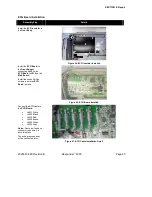
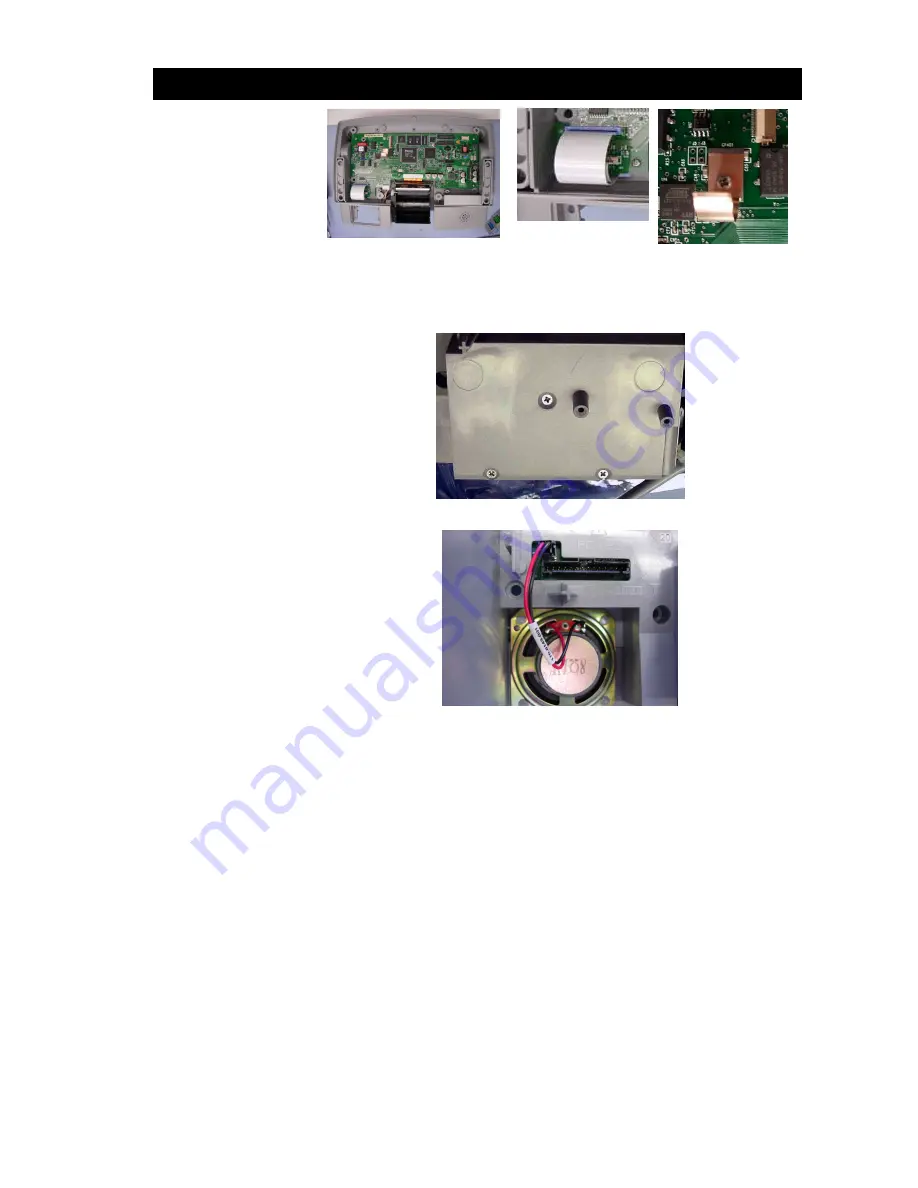
Tuck the ribbon cables
connected to
J210
and
J218
as shown.
Secure the
Main Board
with seven Philips screws
and install the copper
Contact Spring
as shown.
Note:
Ensure the printer
ribbon cable does not twist
during installation.
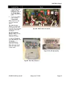
Figure 11: Main Board
Installed
Figure 12: Cable
Detail
Figure 13: Copper
Contact Spring
Installation Detail
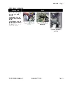
Turn the assembly over
(support the
Printer
so the
cable does not twist) and
secure the printer with three
Phillips screws.
Note:
Tighten the center
screw first to properly align
the
Printer
.
Figure 14: Printer Screws
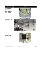
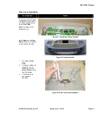
Connect the speaker cable
to
Main Board
J216
.
Figure 15: Speaker Connection


