Chapter 14Standalone controller for RSTi-EP
GFK-2958E
RSTi-EP User Manual
414
Membrane Run/Stop push button
Pressing Membrane Run/Stop push button briefly, will change the state of CPU from
the state it is in to the next state. Switch operation state as given in the following
state diagram:
The
Run/Stop
switch is enabled by default; it can be disabled in PME Hardware Configuration
(HWC) settings.
LED Indicators (LEDs)
Ethernet Status Indicators
There are two LEDs (Yellow/Green) for each Ethernet ports of LAN1 and LAN2, which are
embedded in the RJ-45 connectors. The green LED indicates an Ethernet connection has been
established. The yellow LED indicates packet traffic.
Module status Indicators
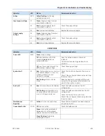
There are three LEDs and one Membrane Push Button on the front panel (The one in
blue color) as shown in the figure. The below table describes the behavior of each
module LED:
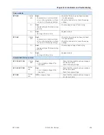
Push Button: Toggles the current mode of the PLC.
LED
LED State
Operating State
OK
On Green
PLC has passed its power-up diagnostics and is functioning properly
Off
Power is not applied or PLC has a problem.
Blinking; All
other LEDs off
PLC in STOP/Halt state; possible watchdog timer fault. If the
programmer cannot connect, cycle power and refer to the
fault tables.
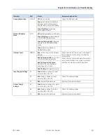
RUN
On Green
PLC is in RUN mode.
Off
PLC is in STOP mode.
Blinking; All
other LEDs off
Indicates that PLC has encountered a fatal error and is
blinking the error code.
Fault
On Green
PLC is in STOP/Faulted mode: a fatal fault has occurred.
Summary of Contents for RSTi-EP
Page 1: ...RSTi EP User Manual GFK 2958E November 2017...
Page 23: ...Chapter 1 Introduction GFK 2958E RSTi EP User Manual 19 Notes...
Page 56: ...Chapter 3 Configuration GFK 2958E RSTi EP User Manual 52 Notes...
Page 183: ...Chapter 5 Detailed Descriptions of I O Modules GFK 2958E RSTi EP User Manual 179 EP 5111...
Page 184: ...Chapter 5 Detailed Descriptions of I O Modules GFK 2958E RSTi EP User Manual 180 EP 5111...
Page 316: ...Chapter 5 Detailed Descriptions of I O Modules GFK 2958E RSTi EP User Manual 312 Notes...
Page 330: ...Chapter 6 Installation GFK 2958E RSTi EP User Manual 326 Notes...
Page 344: ...Chapter 7 Earthing and Shielding GFK 2958E RSTi EP User Manual 340...
Page 345: ...Chapter 7 Earthing and Shielding GFK 2958E RSTi EP User Manual 341 Notes...
Page 385: ...Chapter 8 Web Server GFK 2958E RSTi EP User Manual 381 Notes...
Page 401: ...Chapter 11 Disassembly and Disposal GFK 2958E RSTi EP User Manual 397 Notes...
Page 413: ...Chapter 12 LED Indicators and Troubleshooting GFK 2958E RSTi EP User Manual 409 Notes...
Page 416: ...Chapter 14Accessories and Replacement Parts GFK 2958E RSTi EP User Manual 412 Notes...

