REPLACING CON
TAC
T
ARM ASSEMBLY
For Outside Poles
REMOVE BREAKER COVER
1)
Manually trip breaker
2)
Remove escutcheon plate from breaker covP-r by
unscrewing
4
screws.
3)
Remove breaker cover by unscrewing
4
cover
screws. Note: Lower screws concealed by escutch
eon plate.
For
detailed instructions, see
GEH-3371-A
REMOVE TRIP UNIT
4)
Unscrew hex head bolts but leave in position in
line-conductor holes of trip unit coils.
5)
Unscrew socket head bolts from load-conductor
holes of trip unit coils and remove along with
lock washers and plain washers.
6)
Unscrew round head screws.
Trip unit may now
be
removed from the breaker
base.
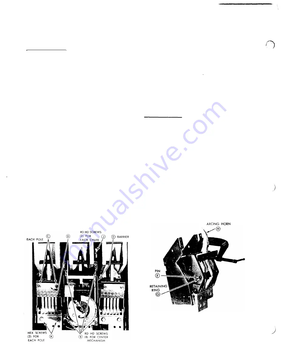
REMOVING CONTACT ARM ASSEMBLIES,
Figure
1.
7)
Remove
6
Hex Head Screws (A) and
8
Round
Head Screws
(B),
using adjustable wrench and
square shank screwdriver to loosen Screws
(B).
NOTE: Threaded plates in back of breaker will
drop free when these screws are removed.
8)
Lift out center mechanism, along with contact
arm assemblies which are attached to Crossbar
(D) . It may be necessary to pry the front mount
ing feet of the center mechanism loose because of
the dowel pins into the base.
9)
Remove Hex Nuts (C), lockwashers and clamp
plates, Contact arms may now be removed.
HEX NUTS
(2)
FOR
CROSSBAR
Figure
1
REPLACING CONTACT ARM ASSEMBLIES
10)
Replace new contact arm assemblies by revers
ing procedure. Before tightening connections
A,
B or C, be sure arcing horn is centered in arc
chute. Tighten Hex Nuts (C) to 50 in. lbs. When
replacing Round Head Screws (B) , make cer
tain threaded plates in back of breaker are in
correct recesses.
11)
When replacing breaker cover, make certain
Barriers (E) fit into proper cover recesses,
otherwise breaker will not operate.
For Center Poles
12)
Follow Steps 1 through
9
for removal of center
mechanism and outside pole contact arms.
13)
Slide Barrier (E) off end of Crossbar (D) .
14)
Remove Hex Nuts (C), lockwashers and clamp
plates, and remove crossbar.
15)
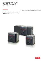
Position C-Clamp, Figure
2
and tighten to re
lieve the pressure of Arcing Horn (H) against
Pin F. Use paper between contact surfaces of
clamp to prevent marring of clamped surfaces.
16)
Remove Retaining Rings
(G)
from each end of
Pin F with Tru-Arc pliers. Withdraw pin.
17)
Install new contact arm assembly by reversing
procedure. NOTE: When replacing Barrier (E),
curved edge is up and chamfered corner towards
line end of breaker.
Figure 2
www . ElectricalPartManuals
. com
www
. ElectricalPartManuals
. com


