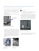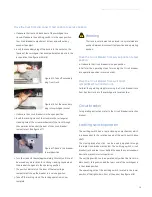
SecoGear 24kV-27kV Air Insulation Switchgear
31
Main Busbar
Rule and Note:
Every 3~4 panels use one Main Busbar. The maximum length of Main Busbar should be less than 4m.
Below is a table indicating Busbar sizing;
Rated current
Busbar type
Cross section (copper)
Main Busbar &
Branch Busbar
(Rectangle)
1250A
Branch
50x8x2
Main
80x10x1
2500A
Branch
120x8x2
Main
120x8x2
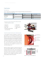
Connection mode of Main Busbar / Branch Busbar
Connection mode of Main Busbar and Grading ring
•
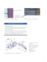
Main Busbar and Branch Busbar
1. Main busbar
2. Wall bushing
3. Support pad
4. Main Busbar & Branch Busbar
joint insulation boot
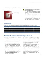
In order to better protect the wall bushing, it is necessary to
add a grading ring in the wall bushing to balance the voltage
between the wall bushing and main busbar. So the grading ring
and the main busbar should be connected before doing the
routine tests and installation of the Switchgear in the field. As
the grading ring is casted into the wall bushing, the wall bushing
and the main busbar should be connected by conductor.
Here, choose connect the bushing and the main busbar on
the outward side of the switchgear for convenience of the
connection. (See Figure 6/16 )
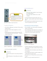
Wall Bushing
Grading Ring
Conductor
Main Busbar
Figure 6/16: Grading Ring and Connecting conductor
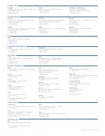
Before the connection of grading ring and main busbar, make
sure the through threaded hole (M5) on the centerline of
main busbar which close the conductor have already tapped
according to the length of the conductor. The length between
the two hole's center of the conductor is 200mm. The distance
between the center of threaded hole and the outer surface of
the wall bushing is 150mm ( See Figure 6/17).
150
Figure 6/17:Position of the threaded hole
5. Branch busbar
6. Insulation Cover
7. Support insulator
8. Spout
1
2
3
4
5
6
7
8

