Chapter 9
Page no. 1220
JC-DR-A-216.fm
GE Healthcare
Senographe DS
Revision 1
Service Information and Procedures Class A 2385072-16-8EN
Job Card D/R A216 - Arm Control Keypads
2
TOOLS
3
REQUIRED EFFORT
Personnel: 1 Field Engineer
Time: 30 minutes
4
SAFETY PRECAUTIONS
WARNING
The Gantry must be powered off.
5
PREREQUISITES
1. Switch off all Senographe electrical power.
2. Prepare a suitable working surface, with protection to avoid scratching the covers.
6
PROCEDURE
! Notice:
Wear an ESD protection strap when removing and replacing keypads.
When removing a cover with its keypad, take care to move it slowly from the structure, to avoid
damage to cables and connectors.
6-1
Removal of Keypads
For each keypad to be removed:
1. Remove the cover which carries the keypad (see
).
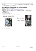
2. Disconnect the keypad cable from the keypad; leave it connected at the Compression Board PL303
or the Tilt Board PL401.
3. Place the cover on the prepared working surface.
4. Check the condition of the cable (W305 or W407). If there is any sign of damage or pinching, a new
cable must be fitted (see
Job Card D/R A215 - Arm Control Keypad Cables
).
5. Remove and keep for reuse the nuts and washers (three sets) which secure the keypad (ratchet
wrench with 11 mm socket (Arm covers) or 6 mm socket (Head covers)).
6. Remove the keypad from the cover.
6-2
Installation of Replacement Keypads
For each keypad to be installed:
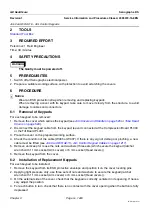
1. Remove the keypad from its ESD protective envelope and position it on the cover locating pins.
2. Applying light pressure only, use three sets of nuts and washers to secure the keypad (ratchet
wrench with 11 mm socket (Arm covers) or 6 mm socket (Head covers)).
3. On the external side of the cover, check that the keypad is correctly centered in its opening. If neces-
sary adjust the position.
4. For each button in turn, check that there is no contact with the cover opening when the button is fully
depressed.

