Chapter 9
Page no. 1268
JC-DR-A-232.fm
GE Healthcare
Senographe DS
Revision 1
Service Information and Procedures Class A 2385072-16-8EN
Job Card D/R A232 - Lift Screw Assembly
6-3-2
If necessary, install the Lift Motor
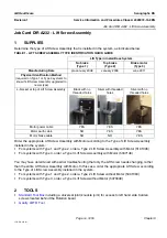
When you receive a new Lift Screw Assembly, it will either be partially or fully constructed, as follows:
•
Lift Screw Assembly with Brake Motor (5337148) - Lift Screw is pre-connected to the Lift Motor
Frame, and the Brake Motor is disconnected
•
Lift Screw Assembly without Motor (5373048) - Lift Screw is pre-connected to the Lift Motor Frame
•
Lift Screw Assembly without Motor (5391083) - Lift Screw is disconnected from the Lift Motor Frame
If necessary (in the case of 5391083), to attach the Lift Screw to the Lift Motor Frame, use the four M6
allen screws supplied with the Lift Screw Assembly to secure the Bearing Cap at the bottom of the Lift
Screw to the Lift Motor Frame. Apply Loctite 270 and a torque of 7
±
1 Nm when securing the M6 allen
screws.
If necessary (in the case of 5337148), to attach the Brake Motor to the bottom of the Lift Screw Lift Motor
Frame, use the following steps:
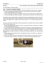
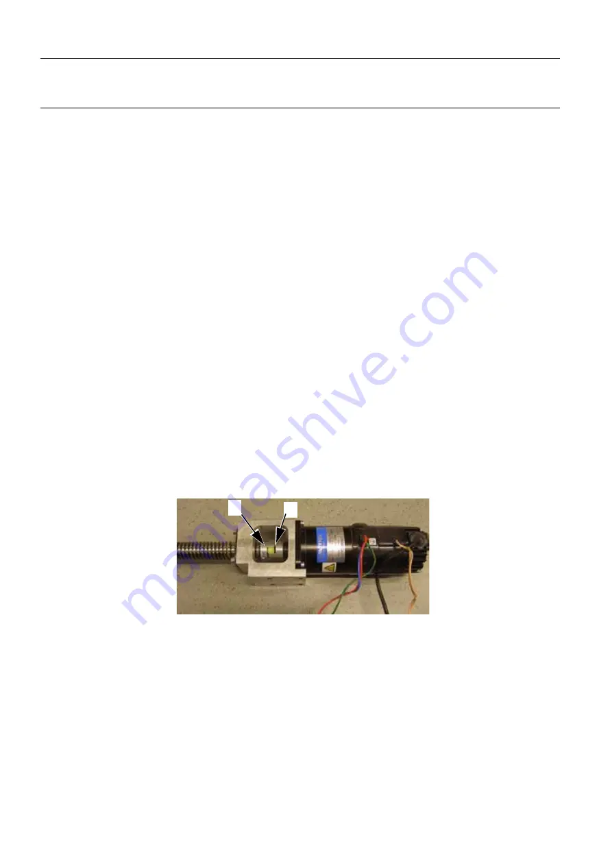
1. Insert the Brake Motor into the Lift Motor Frame, ensuring that the bottom of Lift Screw (1) is aligned
with the top of the Brake Motor (2).
2. Use the four M5 allen screws supplied with the Lift Screw Assembly to secure the Brake Motor to the
Lift Motor Frame. Apply Loctite 270 and a torque of 5
±
1 Nm when securing the M5 allen screws.
If necessary (in the case of 5373048 and 5391083), recouperate the original Motor from the original Lift
Screw Assembly, and attach the Motor to the bottom of the Lift Screw Lift Motor Frame, using the follow-
ing steps:
1. Insert the Motor into the Lift Motor Frame, ensuring that the bottom of Lift Screw (1) is aligned with
the top of the Motor (2).
2. Use the four M5 allen screws from the original Lift Screw Assembly to secure the Motor to the Lift
Motor Frame. Apply Loctite 270 and a torque of 5
±
1 Nm when securing the M5 allen screws.
1
2


