Chapter 9
Page no. 1566
JC-DR-A-405.fm
GE Healthcare
Senographe DS
Revision 1
Service Information and Procedures Class A 2385072-16-8EN
Job Card D/R A405 - HV Cable
6-2
Cable Positioning
•
After the cable has been changed or otherwise disturbed, ensure that you follow the positioning
instructions given in the following sections.
•
To aid correct positioning, the cable carries five reference marks. They are referred to as M1 through
M5, and are positioned on the cable at the following distances from the tube end of the cable:
-
M1; 635 mm
-
M2; 1565 mm
-
M3; 1840 mm
-
M4; 3515 mm
-
M5; 5300 mm
•
When changing the HV cable install new cable ties in the same positions where the original cable ties
were.
6-2-1
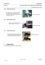
Reference Mark M1
! Notice:
The position of reference mark M1 is critical.
6-2-2
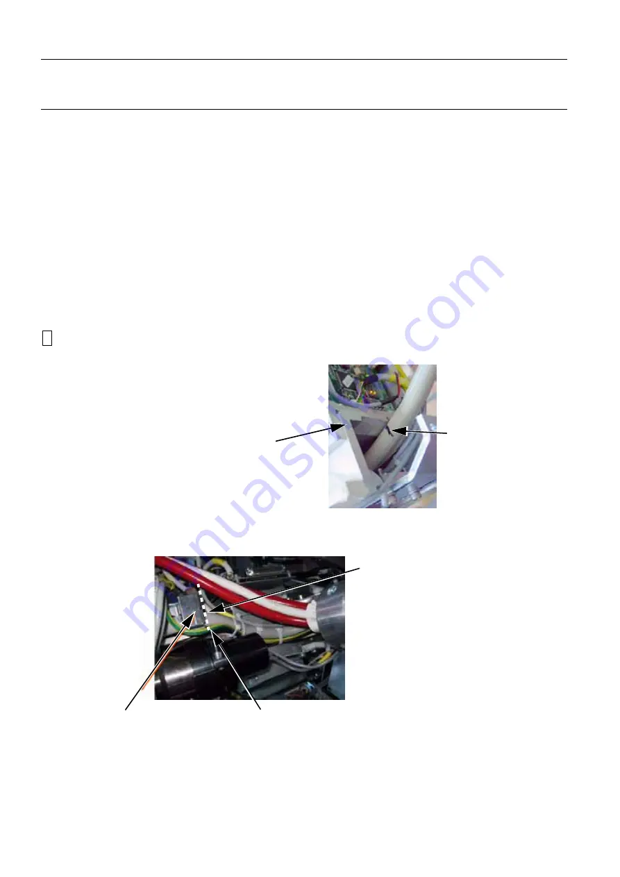
Reference Mark M2.
Mark M1 must be positioned at the point
where the cable from the tube enters the
top of the arm metal tube.
It must be level with the surface of the tube
opening.
The tolerance is ±10 mm.
Reference mark M1
Mark M2 must be positioned at the edge of
the metal clamp which secures the cable
as it exits the bottom of the arm metal tube.
Reference mark M2
Metal
clamp


