GE Healthcare
Senographe DS
Revision 1
Service Information and Procedures Class A 2385072-16-8EN
Job Card CAL A027 - Tube Tilt Calibration
Page no. 1681
Chapter 9
JC-CAL-A-027.fm
Job Card CAL A027 - Tube Tilt Calibration
Chapter 9
1
SUPPLIES
None
2
TOOLS
, included in the Seno. DS Emergency kit.
3
REQUIRED EFFORT
Personnel: 1 Field Engineer
Time: 20 minutes
4
SAFETY PRECAUTIONS
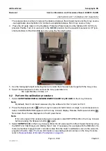
The procedures in this Job Card produce X-rays. Ensure that you take appropriate precautions when
operating with X-rays (for example, stay behind the radiation screen during an X-ray exposure).
5
PREREQUISITES
•
All detector calibrations must have been cleared (select
Service desktop/Calibration/Detector
; then
select Clear
Calibrations
and perform the clear procedure as indicated on the screen).
6
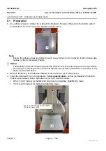
CALIBRATION OF X-RAY TUBE TILT
6-1
Introduction
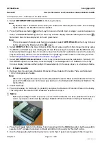
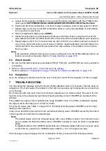
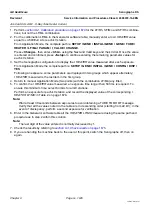
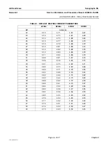
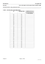
The objective is to evaluate the difference between the real and the theoretical tilt angle. The real tilt
angle depends on mechanical properties (position of the optical fork, tube and others). The difference
can be measured by a specific exposure. After the exposure the ADS receives an image and returns the
distance from the chest wall to the anode heel. The real tilt angle can be determined from this distance:
Real tilt angle = arctan [
]
Source-Image Distance = 660 mm
! Notice:
DO NOT perform Tube Tilt Calibration unless it is strictly necessary
(e.g., after tube replace-
ment or when there is clear evidence of bad calibration parameters).
BEFORE performing Tube Tilt Calibration, clear all detector calibrations
(select
Service
desktop/Calibration/Detector
; then select Clear
Calibrations
and perform the clear procedure as in-
dicated on the screen).
Chest wall to anode heel distance (mm)
Source-Image Distance (mm)


