GE Healthcare
Senographe DS
Revision 1
Service Information and Procedures Class A 2385072-16-8EN
Cable Lay-out and Pin-out
Page no. 307
Chapter 3
Cables.FM
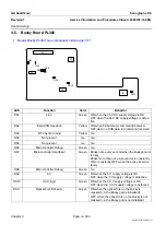
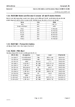
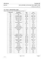
1-39. W213 - POS-Bus 1 between Boards
Rotation Board PL202 J3 to Lift Board PL201 J14.
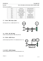
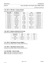
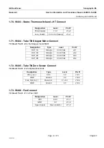
1-40. W215 - Rotation Optical Fork Connect
Rotation Board PL202 J5 to optical detector S203.
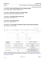
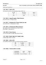
1-41. W216 - Stop Motion Connect (Right)
Emergency Stop R-Button S205 to Interface Board PL104 J6.
1-42. W217 - Stop Motion Connect (Left)
Emergency Stop L-Button S206 to Interface Board PL104 J7.
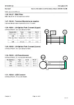
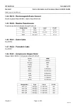
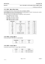
1-43. W218/221 - Clutch Cables
W218:
Clutch B201 to Rotation Board PL202 J8.
W221:
Clutch B201 to Rotation Board PL202 J7.
PIN (PL202)
Designation
Type
Level
PIN (PL201)
PL202/J3-1
H-CAN Network
CAN
Diff 5 / 2.5V
PL201/J14-1
PL202/J3-2
L-CAN Network
CAN
Diff 2.5 / 0V
PL201/J14-2
PL202/J3-3
GND
Ground
0 V
PL201/J14-3
PL202/J3-4
H-RT line 1
RT-CAN
Diff 5 / 2.5 V
PL201/J14-4
PL202/J3-5
L-RT line 1
RT-CAN
Diff 2.5 / 0V
PL201/J14-5
PL202/J3-6
Stop motion
RT
0/+5 V
PL201/J14-6
PL202/J3-7
H-RT line 2
RT-CAN
Diff 5 / 2.5 V
PL201/J14-7
PL202/J3-8
L-RT line 2
RT-CAN
Diff 2.5 / 0V
PL201/J14-8
PL202/J3-9
Reset line
RT
0/+5 V
PL201/J14-9
PL202/J3-10
GND
Ground
0 V
PL201/J14-10
PL202/J3-11
H-RT line 3
RT-CAN
Diff 5 / 2.5 V
PL201/J14-11
PL202/J3-12
L-RT line 3
RT-CAN
Diff 2.5 / 0V
PL201/J14-12
Designation
Type
Level
Pin N°
VCC_Led_1
VCC
5 V
J5-1
GND
Ground
0 V
J5-2
Fork_Opt_Out_1
Open coll.
0 / +5 V
J5-3
GND
Ground
0 V
J5-4


