GE Healthcare
Senographe DS
Revision 1
Service Information and Procedures Class A 2385072-16-8EN
Cable Lay-out and Pin-out
Page no. 319
Chapter 3
Cables.FM
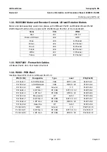
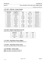
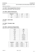
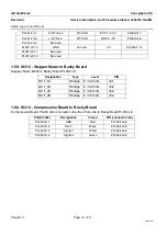
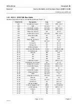
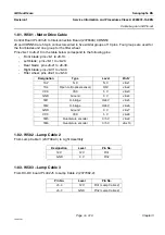
1-81. W501 - Motor Drive Cable
Control Board PL403 J8 to Interconnection Board (2376693) CONN50.
J8 and CONN50 are 50-pin connectors wired in five similar groups of 10 pins. Four groups are used for
the four blades and one group for the filter wheel.
Pins J8-x1 to J8-x10 in the table below correspond to the following pins:
-
Front blade; pins J8-1 to J8-10.
-
Left blade; pins J8-11 to J8-20.
-
Rear blade; pins J8-21 to J8-30.
-
Right blade; pins J8-31 to J8-40.
-
Filter wheel; pins J8-41 to J8-50.
1-82. W502 – Lamp Cable 2
From Lamp Cable 3 (2377082-3) to Light Assembly:
1-83. W503 – Lamp Cable 3
From DC-DC board PL402 J5 to Lamp Cable 2 (2377082-2):
Designation
Type
Level
Pin N°
1S2
N.C
N.C
J8-x1
1S4
Open coll.(optical sensor)
0/5V
J8-x2
VCC
VCC
5 V
J8-x3
GND
Ground
0 V
J8-x4
1M1
H-bridge
0/24 V
J8-x5
1M2
H-bridge
0/24 V
J8-x6
GND
Ground
0 V
J8-x7
VCC
VCC
5 V
J8-x8
1M5
Quadrature encoder
0/5 V
J8-x9
1M6
Quadrature encoder
0/5 V
J8-x10
Designation
Level
Pin No.
12 V
12 V
Pin1
GND
0 V
Pin2
Pin No.
Level
Pin No.
J5-4
12 V
Pin1 (Lamp Cable 2)
J5-3
GND
Pin2 (Lamp Cable 2)

