Chapter 6
Page no. 524
JC-PHY-A-044.fm
GE Healthcare
Senographe DS
Revision 1
Service Information and Procedures Class A 2385072-16-8EN
Job Card PHY A044 - Remove/Reinstall Gantry Covers
7
COLUMN COVERS
! Notice:
When reinstalling these covers, ensure that the covers do not pinch the footswitch cables. Also,
ensure that the footswitch cables are secured with cable ties to prevent any possibility of them be-
ing pulled from their connectors.
7-1
Cable Exit Cover
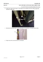
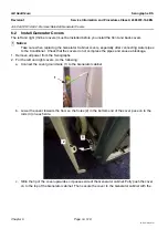
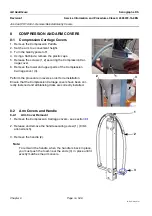
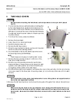
1. Locate the cable exit cover (1) on the right column cover.
2. Release and remove the two screws (2) securing the cable
exit cover (large screwdriver).
3. Pull the cover forward to slide the lip (3) out of the groove and
remove the cable exit cover.
7-2
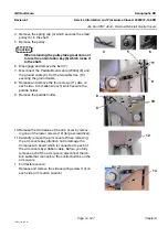
Top Column Covers
1. Power off the Gantry.
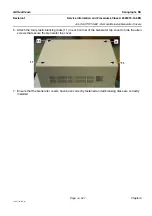
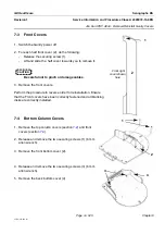
2. Unscrew completely the rear locking screws (1) from each col-
umn half-cover.
3. Unscrew completely the side locking screws (2) from each col-
umn half-cover.
4. Lift and slide the complete half-cover towards you to remove
it.
CAUTION
Be careful not to pinch or damage cables.
Note:
On pilot systems the right cover must be removed before
the left cover.
On production systems the left cover must be removed be-
fore the right cover.
Perform the procedure in reverse order for reinstallation. Ensure
that the Column covers have been correctly fastened and all
blanking disks are correctly installed.
CAUTION
1. When fastening the locking screws, turn the screw until moderate pressure is felt. Never
apply excessive torque; the locking screw or the cover can be permanently damaged.
2. Whenever the Column Top covers are removed, both stop motion buttons must be
tested after reinstallation. Press the stop motion button and check that a HALT error is
triggered.
1
3
2
1
2
Top cover left

