GE Healthcare
Senographe DS
Revision 1
Service Information and Procedures Class A 2385072-16-8EN
Job Card PHY A044 - Remove/Reinstall Gantry Covers
Page no. 529
Chapter 6
JC-PHY-A-044.fm
9
TUBE HEAD COVERS
WARNING
Be careful when touching the Tube Head, as its temperature can be up to 80°C (about
180 °F)
•
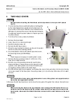
The two tube head covers (left and right) are held together
by four small tapped bars (positioned at references 2-5).
Four screws in each cover hold the cover to these bars. A
fifth screw (1) secures the cover to the tube head chassis.
The GE logo hides the screw number 4. Plastic caps hide
the other screws.
•
To remove the covers, proceed as follows:
1. Remove the face shield.
2. Lower the arm to a convenient height.
3. Switch the Gantry power off.
4. Remove the GE logo (velcro).
5. When the logo has been removed, use the end of an allen
wrench to extract the retaining washer.
6. Use a flat blade to remove the plastic caps which cover
the securing screws (slim flat blade).
Note:
Plastic caps are not present on pilot system covers.
7. Remove the two securing screws (1) at the rear of the
tube (2.5 mm allen wrench).
8. Remove one of the securing screws (5) near the face
shield attachment. These screws are not present on pilot
systems, since pilot systems use a hook to hold the cov-
ers together at this location of the Tube Head.
9. Hold the left and right covers together, and release the covers from each other. Do this by removing
one screw in each of the three pairs of securing screws (2, 3, 4) at the top of the tube (2.5 mm allen
wrench).
CAUTION
The air grille (6) is in two parts, held between the covers. If the grille is not supported when
the covers are separated, it will fall.
10. Remove the left tube head cover and remove the two parts of the grille, then remove the right cover.
CAUTION
When removing the head covers pay attention not to damage the Tilt board which is con-
nected to each of the head covers by a ribbon cable. Before you fully remove each of the
head covers, disconnect the ribbon cable that connects to the control buttons on the head
covers.
1
2
3
4
5
1
6


