Modifications reserved
Page 20/49
OPM_SGS_ISG_M75_M75_2US_V010.doc
Installation Guide
SG Series 750 UL S2
&
SG Series 750 T12 UL S2
3.7
INTER CABINET CONNECTIONS
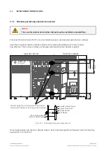
3.7.1 Cabinets positioning and interconnection
NOTE !
The inverter cabinet and rectifier cabinet must be installed on leveled floor.
SG Series 750
&
SG Series 750 T12
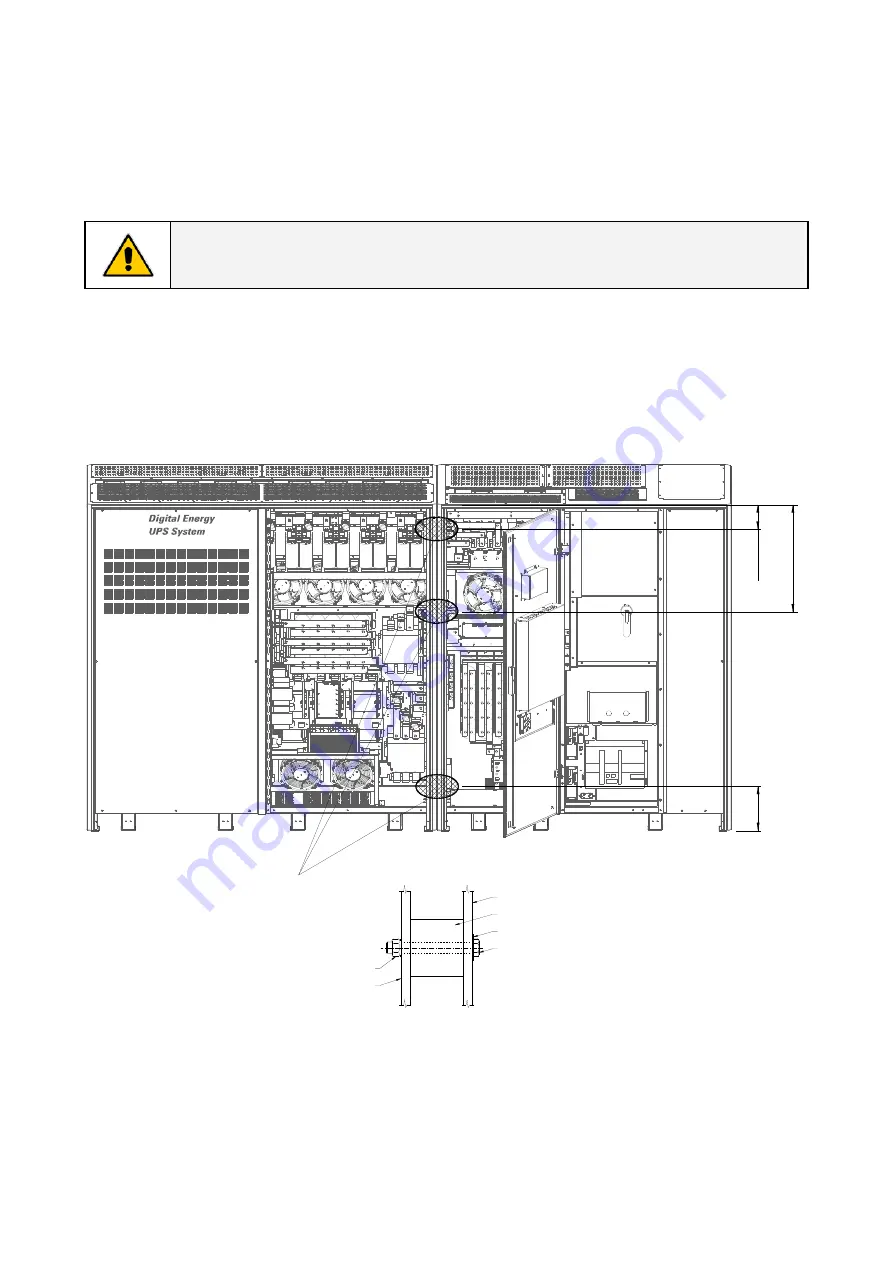
unit, in standard version, are delivered split into two cabinets.
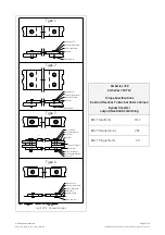
Align them together with the
rectifier cabinet
on the right side (cabinet with control panel).
Pay attention, that no loose cables are trapped when pushing the cabinets together.
Inverter cabinet
Rectifier cabinet
190mm
7.
5"
680mm
26
.8
"
g
Rectifier cabinet frame
Spacer (aluminium)
M8 flat washer
Bolt M8x60
Inverter cabinet frame
M8 Nut with washer
Detail showing the interconnection of the inverter
and rectifier cabinets. To bolt only on the front side.
275mm
10
.8
"
SGS_750_S2_UPS connection cabinets_GE_03US
Fig. 3.7.1-1 Cabinet positioning and interconnection
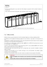
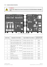
Once finally positioned, the two cabinets have to be connected together with power and control wiring.
See
Section 3.7.2
and
3.7.3
.


