background image


GE


OPM_SGS_USM_10K_40K_0US_V010.doc 

71/88

 Operating 

Manual


SG Series

 10, 20, 30 & 40 kVA 

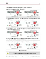
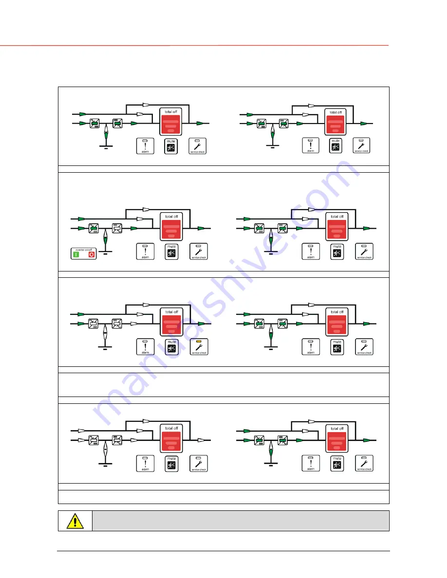
7.4.4  Separate a Unit from the parallel system (System Redundancy) 


Initial status: 

Load supplied from all Inverters


First operated unit 

All other units of the system 


1. Press and hold 

inverter off

 ( O ) key on the Unit, to separate, until the LED 

turns OFF

.


Load

 supplied from 

Inverter(s)

 of the other Unit(s) of the parallel system


First operated unit


All other units of the system


2.  Open Q1 (Pos. O) and, only when the LED service check is ON, press 

total off

button on the Unit to separate

.


First operated unit


All other units of the system


3.  Disconnect the Battery from the Unit to separate

• 

Wait 

5 minutes

 for DC-Link Capacitors discharge.


4.  Disconnect the Utility supply from separated Unit

.


First operated unit


All other units of the system


End of procedure


For any further intervention could nearest 

Service Center

Summary of Contents for SG SERIES 10

Page 1: ...kVA OPERATING MANUAL UNINTERRUPTIBLE POWER SUPPLY Digital Energy TM SG Series 10 20 30 40 kVA Series 0 g General Electric Company 2500 Discovery Blvd Rockwall TX 75032 Telephone 972 290 7400 Fax 972...

Page 2: ...ights reserved The information contained in this publication is intended solely for the purposes indicated The present publication and any other documentation supplied with the UPS system is not to be...

Page 3: ...lete satisfaction Please carefully read the Installation Guide It contains all the necessary information about the installation of the UPS Thank you for choosing GE START UP AND COMMISSIONING A GE Glo...

Page 4: ...s resulting from the use of the information contained in this document WARNING SG Series 10 20 30 and 40 kVA is a product that needs to be installed by a licensed and knowledgeable contractor We recom...

Page 5: ...SAME BATTERY 16 3 5 RECYCLING AT THE END OF SERVICE LIFE 17 4 LAYOUT 18 4 1 LAYOUT SG SERIES 10 AND 20 KVA 18 4 2 LAYOUT SG SERIES 30 AND 40 KVA 19 5 CONTROL PANEL 20 5 1 CONTROL PANEL 20 5 2 TABLE OF...

Page 6: ...d from Q2 on all Units 68 7 4 3 From Manual Bypass Q2 to normal function On line 69 7 4 4 Separate a Unit from the parallel system System Redundancy 71 7 4 5 Reconnect a Unit to a parallel system 72 7...

Page 7: ...removing the sidewalls of the UPS make sure that all earth connections when reassembling are correctly reattached This UPS is intended for use in a controlled indoor environment free of conductive co...

Page 8: ...bjects and jewelry Do not carry metal objects in your pockets where the objects can fall into the Battery Cabinet 2 Tools must have insulated handles and must be insulated so that they will not short...

Page 9: ...symbols are defined WARNING if instruction is not followed injury or serious equipment damage may occur CAUTION internal parts have dangerous voltage present Risk of electric shock PE Earth GND Ground...

Page 10: ...her UPS in the market With today s trend toward power factor corrected loads SG Series can support more total Load than any other UPS available allowing you to support a greater number of today s ente...

Page 11: ...ase AC voltage with constant amplitude and frequency which is completely independent and isolated from the AC input voltage Automatic Bypass The Automatic Bypass consists of a static semiconductor swi...

Page 12: ...rt the critical load Prior to the Battery completely discharging the stop operation alarm shutdown imminent warns the operator that the Battery is almost discharged and the UPS is about to shut down F...

Page 13: ...Bypass In normal operation the Load is supplied by the Inverter When the control system detects a fault in the Inverter an overload condition or a short circuit condition the Automatic Bypass will tr...

Page 14: ...al units can be paralleled in order to achieve output power greater than the maximum power of a single unit The maximum total power shared between the paralleled units is equal to the total installed...

Page 15: ...on and operational status and communicates with all other modules in order to act or react if necessary adapting it to the new conditions 3 3 4 Synchronization All units are identical but one unit is...

Page 16: ...be prepared in advance before the installation The installation must be performed only with the UPS system must be completely shut down The AC Rectifiers input power 5 must be the same with clockwise...

Page 17: ...n rules It does not contain CFCs Carbon Fluor Clorid or HCFCs Halogen Carbon Fluor Clorid Packing material recycling GE in compliance with environment protection uses only environmentally friendly mat...

Page 18: ..._03 Fig 4 1 2 SG Series general view with open doors Fig 4 1 3 Manual operated switches Fig 4 1 4 Control Panel P4 Customer Interface Board Q1 UPS output switch Q2 Manual Bypass switch SNMP SNMP Card...

Page 19: ...FF OFF ON Fig 4 2 2 SG Series general view with open doors Fig 4 2 3 Manual operated switches Fig 4 2 4 Control Panel P4 Customer Interface Board Q1 UPS output switch Q2 Manual Bypass switch SNMP SNMP...

Page 20: ...est Key to test the control panel LED s and buzzer Pressing this key causes all the LED s to light and the buzzer to sound 3 times The push button total off is protected by a red cover By pressing it...

Page 21: ...t down All LED s ON indicate that the Battery is fully charged LED a Yellow Fixed indicating last 25 of Battery backup Blinking indicating Battery backup 5 LED b c d Green EACH ONE INDICATING 25 OF BA...

Page 22: ...metering information for the user to be able to examine the operating status at any time alarms In the event of Utility failures or abnormal functioning the UPS must keep a history of what has happen...

Page 23: ...chine Family name series number P unit number for parallel version from 1 to 8 and power range The status of the load The Load amount as a percentage of the nominal Load referred to the most loaded ph...

Page 24: ...put frequency of the Inverter The synchronization status of the Inverter with respect to Utility INVERTER U1 277V U2 277V U3 277V Frequency 60 0Hz Synchronized metering alarms parameters ok Status Loa...

Page 25: ...operating time for the Inverter in hours MISCELLANEOUS InvHeatsink 45 C UpsOperTime 3125h InvOperTime 2135h metering alarms parameters ok Utility Faults Statistics screen This screen displays The tota...

Page 26: ...rolls forward to the next screen Scrolls backward to the previous screen ok Display the main screen for this mode The events displayed are the standard GE events as described in the Section 6 7 EVENTS...

Page 27: ...iting for the currently selected parameter During parameters mode there is no means to perform scroll back on the display Example of operation within parameters mode Purpose to correct a wrong telepho...

Page 28: ...64340 Tel2 enabled N metering 3 alarms parameters ok Tel1 002186394567 Tel1 enabled N Tel2 004017464340 Tel2 enabled N metering 4 alarms parameters ok Tel1 002186394567 Tel1 enabled N Tel2 00401746434...

Page 29: ...Exits Edit mode and enters parameters mode any changes are discarded Scroll from editable position to editable position Change the currently selected editable position ok Return to parameters mode af...

Page 30: ...mited range of values For example the parameter Printer Baud Rate has the range 600 1200 2400 4800 and 9600 There is no need to edit this parameter digit by digit By pressing the button the next value...

Page 31: ...r wants to abort the action the user sets the parameter to No The actions that can be performed using such software buttons are Print the metering information Print the last 256 events Print the value...

Page 32: ...value you enter is thoroughly checked to be a correct time in the format hh mm ss The time is specified in 24 hour format 2 Protocol Set up PROTOCOL SETUP Modem enabled N Init BEQV1X3 D0S0 2 Alarm N...

Page 33: ...ephone number will be used for dial out Tel3 A third dial out number Tel3 enabled This parameter Y N specifies if the third telephone number will be used for dial out Tel4 A fourth dial out number Tel...

Page 34: ...he data word on the serial line during data transmission 7 or 8 bits are offered as choice Please select 8 bits as this is the only valid value Handshake This parameter is used to determine the commun...

Page 35: ...unit detected the slave unit missing on the communication bus even though switch Q1 is still closed 4100 RECTIFIER FUSES FAILURE The u switch mounted on the Rectifier Input Fuses indicates a blown fu...

Page 36: ...4304 K7 CLOSING FAILURE K7 not closed despite a closing command being issued Signaled by auxiliary contact Load will be supplied by Utility 4305 K7 OPENING FAILURE K7 not open despite an opening comm...

Page 37: ...ening command Be aware the DC Capacitors could remain charged 4520 NO INVERTER POWER The Load supplied by Utility exceeds the Inverter power The Load remains supplied by Utility until the alarm stays...

Page 38: ...reaches the value in parameter 4900 LOAD LOCKED ON INVERTER The Load is locked on Inverter after 3 Load transfers within 30 seconds After time out default 30 sec Bypass will be free 4955 OVERTEMPERAT...

Page 39: ...depends on setting of Parameter 4302 INVERTER CANNOT BE TURNED ON Inverter cannot be switched on because one of the following conditions is still present Over Temperature Low Battery Voltage Inverter...

Page 40: ...580 INVERTER AND UTILITY SYNCHRONIZED The voltages of Inverter and Utility Bypass are synchronized 4582 COMMAND NOT TO SYNCHRONIZE Command not to synchronize with Utility 4583 COMMAND TO SYNCHRONIZE C...

Page 41: ...Customer Place Date Sent by 1 Record the exact UPS status on the panel when the failure appeared 2 On the LCD panel enter the alarms mode and record the alarms messages in the list below indicating at...

Page 42: ...e initial procedure should be performed by an instructed person Check after every step for correct reaction of the UPS LED s on the panel and correct voltage and current measurements before you procee...

Page 43: ...Bypass Utility connects to the output Rectifier starts automatically blinking LED indicates Soft start At the end of Rectifier Soft start LED remains lit 3 Connect the Battery to the UPS by closing th...

Page 44: ...be OFF The LCD screen must display the status LOAD ON BYPASS 2 Close Q2 Pos I Load is now supplied parallel through Bypass and Q2 LED for Manual Bypass lights up 3 Open Q1 Pos O and then press total...

Page 45: ...d LED in Rectifier symbol and LED Battery charge light up 2 Open Q2 Pos O LED Manual Bypass turns OFF 3 Connect the Battery to the UPS by closing the Battery Switch or Fuses in case of External Batter...

Page 46: ...verter 1 Press total off button Load is disconnected from UPS Rectifier is shut down and all output and input contactors will be opened LED s Rectifier Inverter and Load are OFF 2 Open Q1 Pos O LED se...

Page 47: ...and the Rectifier starts Output connects to Bypass Utility Rectifier starts with blinking LED At the end of Soft start the LED remains lit The LCD screen shows LOAD ON BYPASS Press mute to reset alarm...

Page 48: ...ation of EPO Emergency Power Off with Utility available All Contacts are open Rectifier Inverter and Static Switch shutdown 1 Reset the EPO Emergency Power Off button Press mute to reset alarm and buz...

Page 49: ...n Pos O 1 Connect the Utility power on the UPS Power supply starts up Indicated with flashing alarm and buzzer sound LED s as indicated will be lit Press mute to reset alarm and buzzer 2 Close Q1 Pos...

Page 50: ...verter 1 Press total off button Load is disconnected from UPS Rectifier is shut down and all output and input contactors will be opened LED s Rectifier Inverter and Load are OFF 2 Open Q1 Pos O LED se...

Page 51: ...tal off by pressing and holding the total off button and the inverter on I key simultaneously until the Rectifier starts 2 Connect the Battery to the UPS by closing the Battery Switch or Fuses in case...

Page 52: ...w Points 1 through 3 UPS panel after activation of EPO Emergency Power Off with Utility available All Contacts are open Rectifier Inverter and Static Switch shutdown 1 Reset the EPO Emergency Power Of...

Page 53: ...m and buzzer sounds LED s as indicated will be lit Press mute to reset alarm and buzzer First operated unit All other units of the system 2 Close Q1 Pos I on all Units When closing Q1 on the last unit...

Page 54: ...nit All other units of the system 5 Press inverter on I key on all other units Do not start the next Inverter until the sequence of the previous ends As soon as the output power of the Inverters is su...

Page 55: ...ility supply First operated unit All other units of the system 2 Close Q2 Pos I on all Units Load is now supplied from Utility in parallel from Bypass and Manual Bypass Q2 of all Units First operated...

Page 56: ...nit All other units of the system 1 Close Q1 Pos I on all Units The Rectifiers will start automatically and at the closure of Q1 of the last Unit the Bypass of all Units will be activated First operat...

Page 57: ...on the main screen the status LOAD ON INVERTER First operated unit All other units of the system 5 Press inverter on I key on all other units Do not start the next Inverter until the sequence of the p...

Page 58: ...r s of the other Unit s of the parallel system First operated unit All other units of the system 2 Open Q1 Pos O and only when the LED service check is ON press total off button on the Unit to separat...

Page 59: ...Rectifier starts automatically First operated unit All other units of the system 3 Connect the Battery in case of External Battery to the UPS on the separated Unit by closing the external Battery Swi...

Page 60: ...erters First operated unit All other units of the system 1 Press total off button on any one on the Units Load is disconnected from UPS Rectifier and Inverter are shut down and all output and input Co...

Page 61: ...connect the Battery in case of External Battery from all Units Wait 5 minutes for DC Link Capacitors discharge First operated unit All other units of the system 4 Disconnect the Utility supply from al...

Page 62: ...l off by pressing and holding the total off button and then the inverter on I key on any of the Units simultaneously until Load is supplied from Bypass and the Rectifiers start System output connects...

Page 63: ...on the main screen the status LOAD ON INVERTER First operated unit All other units of the system 4 Press inverter on I key on all other units Do not start the next Inverter until the sequence of the p...

Page 64: ...l after activation of EPO Emergency Power Off with Utility available All Contacts are open Rectifier Inverter and Static Switch shutdown First operated unit All other units of the system 1 Reset the E...

Page 65: ...LED indicates Load on Inverter and the LCD must display on the main screen the status LOAD ON INVERTER First operated unit All other units of the system 5 Press inverter on I key on all other Units Do...

Page 66: ...ly starts up Indicated with flashing alarm and buzzer sounds LED s as indicated will be lit Press mute to reset alarm and buzzer First operated unit All other units of the system 2 Connect the Battery...

Page 67: ...nit All other units of the system 5 Press inverter on I key on all other units Do not start the next Inverter until the sequence of the previous ends As soon as the output power of the Inverters is su...

Page 68: ...ll transfer to Utility supply First operated unit All other units of the system 2 Close Q2 Pos I on all Units Load is now supplied from Utility in parallel from Bypass and Manual Bypass Q2 of all Unit...

Page 69: ...operated unit All other units of the system 1 Connect the Battery to all Units by closing the external Battery Switch es or Fuses 2 Close Q1 Pos I on all Units The Rectifiers will start automatically...

Page 70: ...on the main screen the status LOAD ON INVERTER First operated unit All other units of the system 5 Press inverter on I key on all other units Do not start the next Inverter until the sequence of the p...

Page 71: ...ied from Inverter s of the other Unit s of the parallel system First operated unit All other units of the system 2 Open Q1 Pos O and only when the LED service check is ON press total off button on the...

Page 72: ...s of the system 2 Connect the Battery to the UPS separated by closing the external Battery Switch or Fuses 3 Close Q1 Pos I on the separated Unit Rectifier starts automatically First operated unit All...

Page 73: ...erters First operated unit All other units of the system 1 Press total off button on any one on the units Load is disconnected from UPS Rectifier and Inverter are shut down and all output and input co...

Page 74: ...0 40 kVA 3 Disconnect the Battery from all Units Wait 5 minutes for DC Link Capacitors discharge First operated unit All other units of the system 4 Disconnect the Utility supply from all Units All LE...

Page 75: ...m 1 Reset total off by pressing and holding the total off button and then the inverter on I key on any of the Units simultaneously until Load is supplied from Bypass and the Rectifiers start System ou...

Page 76: ...on the main screen the status LOAD ON INVERTER First operated unit All other units of the system 4 Press inverter on I key on all other units Do not start the next Inverter until the sequence of the p...

Page 77: ...ff with Utility available All Contacts are open Rectifier Inverter and Static Switch shutdown First operated unit All other units of the system 1 Reset the EPO Emergency Power Off button Press mute to...

Page 78: ...TER First operated unit All other units of the system 5 Press inverter on I key on all other Units Do not start the next Inverter until the sequence of the previous ends As soon as the output power of...

Page 79: ...def RL2 1 12 13 2 14 3 15 4 16 5 17 6 18 7 19 8 20 9 21 10 22 11 1 14 9 1 X1 J2 J3 SGT5000_100 150_Customer interface_01 J5 J4 XA 2 1 XB 1 2 3 4 1 2 3 4 JP3 Fig 8 1 1 Customer interface NO normally o...

Page 80: ...ion mode These signals are available either on connector J2 sub D female 25 pin or terminal blocks X1 The meaning of the alarms on the free contacts in standard configuration default is the following...

Page 81: ...elay of Battery recharging during the generator operation In a parallel system a separate NO Normally Open contact must be connected individually to each unit 8 1 5 AUX external Maintenance Bypass If...

Page 82: ...he Terminal XB and the Jumper JP3 on P4 Customer Interface when the cables have been already connected on XB or J2 In a parallel system a separate NC Normally Closed contact must be connected individu...

Page 83: ...Management System NMS or by our applications for instance JUMP which uses this information to determine the state of the UPS in order to guarantee safe and orderly shutdown of the server when needed...

Page 84: ...oard The alarms on free potential contacts can be connected on terminals X1 instead J2 see correlation X1 J2 in chapter 8 1 Mute Test max 985ft 300m yellow brown white yellow 1 2 4 3 5 brown green 7 6...

Page 85: ...ir circulation in the unit and in the Battery We recommend replacement of the fans in the units every 20 000 hours 10 1 3 Other components with limited lifetime We recommend the replacement of compone...

Page 86: ...shut down periods of the UPS system a Cleaning a visual inspection and a mechanical inspection of the UPS modules b Replacement of defective parts or the preventive replacement of parts with a define...

Page 87: ...l SG Series 10 20 30 40 kVA 11 NOTES 11 1 NOTES FORM It is recommended to note in this section Notes with date and short description all the operations performed on the UPS as maintenance components r...

Page 88: ...or ii making available F O B at Seller s facility place of manufacture or other mutually agreed upon point of shipment any necessary repaired or replacement parts provided however that prior to repai...

Reviews: