GE Analytical Instruments ©2010
11 of 226
DLM 74001-04 Rev. A
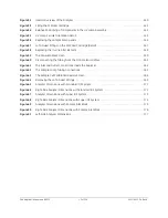
List of Figures
Figure 1
Analyzer Schematic (Shown with Standard iOS). . . . . . . . . . . . . . . . . . . . . . . . . . . . . . . . . . . . . . . . . . . . . . . 42
Figure 2
Wiring AC Power . . . . . . . . . . . . . . . . . . . . . . . . . . . . . . . . . . . . . . . . . . . . . . . . . . . . . . . . . . . . . . . . . . . . . . . . . . . . 49
Figure 3
Wiring Diagram for the 4-20 mA Connection . . . . . . . . . . . . . . . . . . . . . . . . . . . . . . . . . . . . . . . . . . . . . . . . . 51
Figure 4
Wiring Option for Binary Input Using Analyzer’s Internal Supply . . . . . . . . . . . . . . . . . . . . . . . . . . . . . . . 52
Figure 5
Wiring Option for Binary Input Using External Supply . . . . . . . . . . . . . . . . . . . . . . . . . . . . . . . . . . . . . . . . . 53
Figure 6
Input and Output Connectors. . . . . . . . . . . . . . . . . . . . . . . . . . . . . . . . . . . . . . . . . . . . . . . . . . . . . . . . . . . . . . . . 53
Figure 7
Locating The DI Water Cartridge . . . . . . . . . . . . . . . . . . . . . . . . . . . . . . . . . . . . . . . . . . . . . . . . . . . . . . . . . . . . . 56
Figure 8
Filling the DI Water Cartridge . . . . . . . . . . . . . . . . . . . . . . . . . . . . . . . . . . . . . . . . . . . . . . . . . . . . . . . . . . . . . . . . 57
Figure 9
Removing the John Guest Fitting . . . . . . . . . . . . . . . . . . . . . . . . . . . . . . . . . . . . . . . . . . . . . . . . . . . . . . . . . . . . 58
Figure 10
The Sievers 500 RL On-Line TOC Analyzer Main Screen. . . . . . . . . . . . . . . . . . . . . . . . . . . . . . . . . . . . . . . . 68
Figure 11
The Setup Tab . . . . . . . . . . . . . . . . . . . . . . . . . . . . . . . . . . . . . . . . . . . . . . . . . . . . . . . . . . . . . . . . . . . . . . . . . . . . . . 70
Figure 12
The Data Tab . . . . . . . . . . . . . . . . . . . . . . . . . . . . . . . . . . . . . . . . . . . . . . . . . . . . . . . . . . . . . . . . . . . . . . . . . . . . . . . 71
Figure 13
Specifying a Start Date on the View Data Screen . . . . . . . . . . . . . . . . . . . . . . . . . . . . . . . . . . . . . . . . . . . . . 73
Figure 14
Graphing the Data History . . . . . . . . . . . . . . . . . . . . . . . . . . . . . . . . . . . . . . . . . . . . . . . . . . . . . . . . . . . . . . . . . . 75
Figure 15
The I/O Tab (With Ethernet Port Installed) . . . . . . . . . . . . . . . . . . . . . . . . . . . . . . . . . . . . . . . . . . . . . . . . . . . . 76
Figure 16
The Modbus Screen . . . . . . . . . . . . . . . . . . . . . . . . . . . . . . . . . . . . . . . . . . . . . . . . . . . . . . . . . . . . . . . . . . . . . . . . 83
Figure 17
The Maintenance Tab . . . . . . . . . . . . . . . . . . . . . . . . . . . . . . . . . . . . . . . . . . . . . . . . . . . . . . . . . . . . . . . . . . . . . . . 86
Figure 18
The Advanced Menu with One Program Language Loaded . . . . . . . . . . . . . . . . . . . . . . . . . . . . . . . . . . . 88
Figure 19
The Standard iOS System. . . . . . . . . . . . . . . . . . . . . . . . . . . . . . . . . . . . . . . . . . . . . . . . . . . . . . . . . . . . . . . . . . . . 97
Figure 20
The Super iOS System . . . . . . . . . . . . . . . . . . . . . . . . . . . . . . . . . . . . . . . . . . . . . . . . . . . . . . . . . . . . . . . . . . . . . . 98
Figure 21
The Sample Inlet Block . . . . . . . . . . . . . . . . . . . . . . . . . . . . . . . . . . . . . . . . . . . . . . . . . . . . . . . . . . . . . . . . . . . . . . 98
Figure 22
Menu Map — Menu Lockout Off (Requires Calibration Passwords) . . . . . . . . . . . . . . . . . . . . . . . . . . . . 102
Figure 23
Menu Map — DataGuard (Optional Upgrade) . . . . . . . . . . . . . . . . . . . . . . . . . . . . . . . . . . . . . . . . . . . . . . . . 103
Figure 24
Reviewing TC and IC Values from a Single-Point Calibration . . . . . . . . . . . . . . . . . . . . . . . . . . . . . . . . . . 119
Figure 25
Reviewing Conductivity Values from a Single-Point Calibration . . . . . . . . . . . . . . . . . . . . . . . . . . . . . . . 119
Figure 26
The First Summary Screen in a Multi-Point Calibration . . . . . . . . . . . . . . . . . . . . . . . . . . . . . . . . . . . . . . . 122
Figure 27
The Second Summary Screen in a Multi-Point Calibration . . . . . . . . . . . . . . . . . . . . . . . . . . . . . . . . . . . . 123
Figure 28
The Third Summary Screen in a Multi-Point Calibration . . . . . . . . . . . . . . . . . . . . . . . . . . . . . . . . . . . . . . 123
Figure 29
The Accuracy, Precision, and Verification Summary Screen, Part 1 . . . . . . . . . . . . . . . . . . . . . . . . . . . 126
Figure 30
The Accuracy, Precision, and Verification Summary Screen, Part 2 . . . . . . . . . . . . . . . . . . . . . . . . . . . 126
Figure 31
System Suitability Summary Screen . . . . . . . . . . . . . . . . . . . . . . . . . . . . . . . . . . . . . . . . . . . . . . . . . . . . . . . . 129
Summary of Contents for Sievers 500 RL
Page 8: ...GE Analytical Instruments 2010 8 of 226 DLM 74001 04 Rev A ...
Page 10: ...GE Analytical Instruments 2010 10 of 226 DLM 74001 04 Rev A ...
Page 36: ...GE Analytical Instruments 2010 36 of 220 DLM 74001 04 Rev A ...
Page 66: ...GE Analytical Instruments 2010 66 of 226 DLM 74001 04 Rev A Chapter 3 Installation ...
Page 152: ...GE Analytical Instruments 2010 152 of 226 DLM 74001 04 Rev A Chapter 7 Maintenance ...
Page 170: ...GE Analytical Instruments 2010 170 of 226 DLM 74001 04 Rev A Chapter 8 Troubleshooting ...
Page 178: ...Appendix A GE Analytical Instruments 2010 178 of 186 DLM 74001 04 Rev A ...
Page 185: ...Notes GE Analytical Instruments 2010 185 of 186 DLM 74001 04 Rev A 186 ...
Page 186: ...Notes GE Analytical Instruments 2010 186 of 186 DLM 74001 04 Rev A 186 ...


