GE Analytical Instruments ©2010
49 of 226
DLM 74001-04 Rev. A
Chapter 3: Installation
Figure 2: Wiring AC Power
Installing the Analog Outputs and Alarms
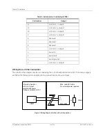
The Analyzer offers four alarm and three 4-20 mA outputs, via three terminal blocks that are arranged
horizontally in the electrical enclosure. The Analyzer also has one Ethernet port. Consult Tables 1 through 3
below for a list of functions on each terminal block. The output and alarm connections should be installed by a
qualified electrician.
Route the cables to the terminal strips through the pass-through port on the left side of the bulkhead, labeled
CONTROL
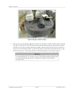
. Remove the pass-through cap by opening the Analyzer’s front panel and loosening the wing nut that
secures the cover from inside the Analyzer. Secure the PVC conduit connector (“strain relief” hub) and washer to
the conduit and the Analyzer bulkhead in the normal manner. Wire should be 22-12 AWG, rated to 300 Volts.
Strip length should be 8-9 mm (.33 in). To attach the output connections, first remove the terminal block from the
I/O board by firmly grasping the terminal block and pulling it straight out from the board (note the orientation of
the terminal block before removing). Completely loosen the screw for each pin you are connecting, insert the
wire, tighten the screw, and then gently pull on each connection to make sure the connection is secure. Then,
replace the terminal blocks.
Starting from the left, the terminal blocks are as follows:
1. The first terminal block (TB2) is for two alarm outputs and binary inputs.
2. The second terminal block (TB1) is for two additional alarm outputs.
Summary of Contents for Sievers 500 RL
Page 8: ...GE Analytical Instruments 2010 8 of 226 DLM 74001 04 Rev A ...
Page 10: ...GE Analytical Instruments 2010 10 of 226 DLM 74001 04 Rev A ...
Page 36: ...GE Analytical Instruments 2010 36 of 220 DLM 74001 04 Rev A ...
Page 66: ...GE Analytical Instruments 2010 66 of 226 DLM 74001 04 Rev A Chapter 3 Installation ...
Page 152: ...GE Analytical Instruments 2010 152 of 226 DLM 74001 04 Rev A Chapter 7 Maintenance ...
Page 170: ...GE Analytical Instruments 2010 170 of 226 DLM 74001 04 Rev A Chapter 8 Troubleshooting ...
Page 178: ...Appendix A GE Analytical Instruments 2010 178 of 186 DLM 74001 04 Rev A ...
Page 185: ...Notes GE Analytical Instruments 2010 185 of 186 DLM 74001 04 Rev A 186 ...
Page 186: ...Notes GE Analytical Instruments 2010 186 of 186 DLM 74001 04 Rev A 186 ...

