GE Analytical Instruments ©2010
64 of 226
DLM 74001-04 Rev. A
Chapter 3: Installation
1. Select the
Maintenance
tab.
2. Press the
Advanced
button.
3. Press the
Print Constants
button.
4. Press each of the five buttons, one at a time, to print the different constants.
Set Up Data I/O
If you installed binary input, alarms, or the 4-20 mA output, configure settings for those features now. Select the
I/O tab and configure the appropriate settings. Note that you may need to consult with your remote operations
center to determine some values. See page 77 through page 78 for details on configuring these settings.
Step 9: Rinsing the Analyzer
Before placing the Analyzer into normal operation, you should rinse the Analyzer for 12 hours by running it in
Rinse mode and then letting it run in On-Line mode.
1. Select the
Maintenance
tab.
2. Press the
Advanced
button, then press the
Advanced Setup
button.
3. Press the
Auto Restart
button. Make sure
Rinse Down
is set to
On
. If it is set to
Off
, press the
Rinse
Down
button, and then press the
On
button.
4. Press the
Back
button, then press the
Rinse
button.
5. The Analyzer will run in Rinse mode, and then will automatically switch into On-Line mode. Let the
Analyzer run for 12 hours. No data will be reported for the Rinse mode.
6. After 12 hours, press the
Stop Analysis
button.
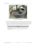
7. Open the Analyzer case and again visually inspect the Analyzer for leaks, especially around the DI water
cartridge. If a leak is detected, make sure all fittings are tight and secure. Also confirm the water level in
the DI water cartridge and, if necessary, turn off the Analyzer and add more water.
8. Close the Analyzer case.
The Analyzer is now ready to take valid TOC measurements. If you want to customize additional settings, do so
now; consult Chapter 4: Basic Analyzer Operation for details.
Note:
If the TOC level in your sample water is typically below 50 ppb, schedule a regular
TOC Autozero. See “Programming the TOC Autozero” on page 105 for details.
Summary of Contents for Sievers 500 RL
Page 8: ...GE Analytical Instruments 2010 8 of 226 DLM 74001 04 Rev A ...
Page 10: ...GE Analytical Instruments 2010 10 of 226 DLM 74001 04 Rev A ...
Page 36: ...GE Analytical Instruments 2010 36 of 220 DLM 74001 04 Rev A ...
Page 66: ...GE Analytical Instruments 2010 66 of 226 DLM 74001 04 Rev A Chapter 3 Installation ...
Page 152: ...GE Analytical Instruments 2010 152 of 226 DLM 74001 04 Rev A Chapter 7 Maintenance ...
Page 170: ...GE Analytical Instruments 2010 170 of 226 DLM 74001 04 Rev A Chapter 8 Troubleshooting ...
Page 178: ...Appendix A GE Analytical Instruments 2010 178 of 186 DLM 74001 04 Rev A ...
Page 185: ...Notes GE Analytical Instruments 2010 185 of 186 DLM 74001 04 Rev A 186 ...
Page 186: ...Notes GE Analytical Instruments 2010 186 of 186 DLM 74001 04 Rev A 186 ...


