GE Analytical Instruments ©2010
89 of 226
DLM 74001-04 Rev. A
Chapter 4: Basic Analyzer Operation
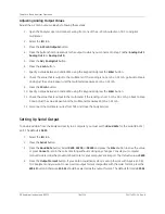
2. Press the
Advanced
button.
3. Press the
Warn/Error Out
button
• Press
Print History
to output the history to the printer.
• Press
Export History
to output the history to the USB flash memory drive.
Saving System Settings
You can archive settings to the USB port and restore them at a later time. This feature provides a backup
mechanism in the event that you need to return to previous settings, including calibration and user-configurable
settings. Save your Analyzer’s system settings as follows:
1. Select the
Maintenance
tab.
2. Press the
Advanced
button.
3. Press the
USB I/O
button. Make sure that the USB flash memory drive is attached to the USB port.
4. Press the
Save System
button.
To use the restore feature, be sure that the USB flash memory drive containing the previously exported data is
attached to the Analyzer’s USB port, repeat Steps 1 through 3 above, and select
Restore System
.
Printing the Constants Values
Calibration constants and other key parameters are stored in non-volatile memory. If you have a printer
attached to the Analyzer, you can print these settings for future reference by following these steps:
1. Select the
Maintenance
tab.
2. Press the
Advanced
button.
3. Press the
Print Constants
button, and then select one of the following to print:
•
System Configuration
— Prints basic user-configurable settings.
•
System Constants
— Prints the factory-set constants for each conductivity cell.
•
Calibration Constants
— Prints constants set by the most recent calibration.
•
Consumables Settings
— Prints usage and expected life information about consumables.
•
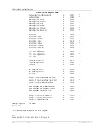
Stage 1 Table
— Prints the Stage 1 Table for temperature and conductivity requirements, according
to the pharmacopeia currently selected for the Analyzer. The button label also indicates the
applicable pharmacopeia, such as
USP 645
or
EP WFI 2.2.38
. Conductivity must be activated, along
with one of the available pharmacopeia selections (JP TOC and JP COND excepted) for this button to
display.
Summary of Contents for Sievers 500 RL
Page 8: ...GE Analytical Instruments 2010 8 of 226 DLM 74001 04 Rev A ...
Page 10: ...GE Analytical Instruments 2010 10 of 226 DLM 74001 04 Rev A ...
Page 36: ...GE Analytical Instruments 2010 36 of 220 DLM 74001 04 Rev A ...
Page 66: ...GE Analytical Instruments 2010 66 of 226 DLM 74001 04 Rev A Chapter 3 Installation ...
Page 152: ...GE Analytical Instruments 2010 152 of 226 DLM 74001 04 Rev A Chapter 7 Maintenance ...
Page 170: ...GE Analytical Instruments 2010 170 of 226 DLM 74001 04 Rev A Chapter 8 Troubleshooting ...
Page 178: ...Appendix A GE Analytical Instruments 2010 178 of 186 DLM 74001 04 Rev A ...
Page 185: ...Notes GE Analytical Instruments 2010 185 of 186 DLM 74001 04 Rev A 186 ...
Page 186: ...Notes GE Analytical Instruments 2010 186 of 186 DLM 74001 04 Rev A 186 ...


