background image

Compact 24” Washer

WSLS1500J
WSLP1500J

Summary of Contents for Spacemaker WSLS1500J

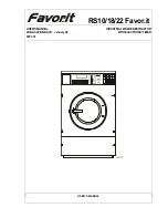
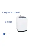
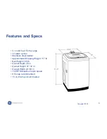
Page 1: ...Compact 24 Washer WSLS1500J WSLP1500J...

Page 2: ...for the interpretation of this information nor can it assume any liability in connection with its use WARNING To avoid personal injury disconnect power before servicing this product If electrical powe...

Page 3: ...uired to use safety glasses with side shields cut resistant Dyneema gloves steel toe shoes for all repairs Dyneema Cut Resistant Glove Safety Glasses must be compliant with ANSI Z87 1 2003 Prescriptio...

Page 4: ...4 Copyright 2009 Warranty...

Page 5: ...5 Copyright 2009 W S L S 1 5 0 0 J Nomenclature Product W Washer Model S Space maker Basket Size L Large Product Type S Stationary P Portable Engineering Revision...

Page 6: ...t Extra Large 14 wash cycles Stainless steel basket Approximate Shipping Weight 117 lb Net Weight 106 lb Overall Depth 26 in Overall Height 37 1 2 in Overall Width 23 5 8 in 700 RPM Maximum spin speed...

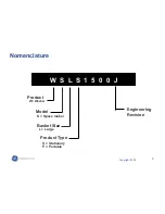
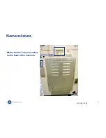
Page 7: ...7 Copyright 2009 Nomenclature Model number in two locations on the back of the machine...

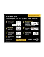
Page 8: ...8 Copyright 2009...

Page 9: ...9 Copyright 2009 Leveling Washer Check to ensure the washer is level With the door open the spin basket should be centered in the opening as shown in the leveled view...

Page 10: ...10 Copyright 2009 Leveling Washer Pull lock lever out and level front of machine Push lever back in to secure setting Close up view Remove 2 screws to replace leg assembly 1 on other side not pictured...

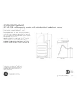
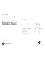
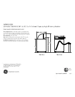
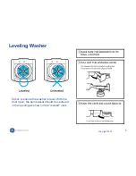
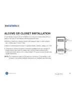
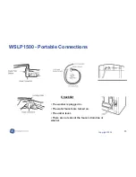
Page 11: ...11 Copyright 2009 Installation...

Page 12: ...12 Copyright 2009 Installed with Dryer DSDR24F Rack...

Page 13: ...13 Copyright 2009 WSLP1500 Portable Connections The washer is plugged in The water faucets are turned on The unit is level There are no leaks at the faucet drain line or washer Checklist...

Page 14: ...ressing the OPTIONS pad again will change to 2 The customer can scroll up to 5 rinse cycles Once the customer stops scrolling the display will automatically add additional cycles and time to the Est M...

Page 15: ...3 The control can add or subtract spin time by scrolling through the OPTIONS pad after the Spin cycle has been initiated The increments are smaller and the logic is different Customer can increase spi...

Page 16: ...0 seconds Pauses and continues fill for about 10 seconds then agitates It repeats this process in varying degrees and stages 4 times before the tub is at the correct water level and the machine comple...

Page 17: ...lock the control in the standby mode Press and hold LOAD and OPTIONS pads simultaneously for 3 seconds while machine is in a cycle Display alternates between CL and time remaining Control Features ST...

Page 18: ...remains active If the customer selects a specific LOAD size manually LOAD SENSING is deactivated and the pressure sensor fills accordingly If the customer leaves load sensing active and presses the ST...

Page 19: ...n is canceled when water level key is pressed prior to the completion of weight recognition function If the current water level is above the lowest level at the beginning of weight sensing it is autom...

Page 20: ...CLE Set the CYCLES selection to CUSTOM CYCLE Select TEMP and OPTIONS choices Press START pad Control remembers and the next time those setting will be displayed Note CUSTOM CYCLE always utilizes Load...

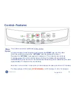
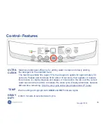
Page 21: ...21 Copyright 2009 Control Removal Remove two plugs and screws...

Page 22: ...22 Copyright 2009 Control Removal Pry out small rubber plugs Remove Phillips head screws Slide Control Panel to the left to release Lift up from rear to release front clips Note mini manual location...

Page 23: ...23 Copyright 2009 Control Removal Remove 5 Phillips head screws that secure the PCB to the control panel...

Page 24: ...PCB when installing the PCB to the control panel route the wiring utilizing the wire tabs Make sure all screw locations on the PCB fully contact the control panel before installing the screws Before...

Page 25: ...ns CN1 Door switch Unbalance switch Pressure sensor CN2 Line Voltage CN3 Neutral Neutral to Water valve solenoids CN4 Washing motor CN5 Washing motor Washing motor condenser CN6 Water valve solenoids...

Page 26: ...26 Copyright 2009 Control Wire Positions Note the schematic drawing and the actual wire locations on the 11 pin CN1 connector...

Page 27: ...27 Copyright 2009 Control Testing Pins are very small and tight Meter leads may not fit...

Page 28: ...the water valve pressure sensor unbalance switch fuse and lid springs The back cover is held to the rear of the top cover with 2 Phillips head screws and 4 tabs The tabs are located inside the back c...

Page 29: ...29 Copyright 2009 Component Location 1 2 3 4 1 Pressure Sensor 2 Water Valve 3 Unbalanced Switch 4 Line fuse Neutral Wire Harness Fiberglass Covers...

Page 30: ...utral line of the top cover wire harness the fuse is rated at 250 VAC 12 amps the fuse and fuse holder are located at the right rear corner of the top cover Lift the fuse holder from the recess in the...

Page 31: ...ed through a hole in the top cover The normally open contacts will close when the lid is closed An open unbalance switch will Cause Lo lid open to appear in the display Stop the wash cycle Stop the dr...

Page 32: ...y 3 4 inch toward the rear of the cabinet The first two 2 times the switch is tripped the washer stops time is added to the display fills with water agitates then spins again If the switch is tripped...

Page 33: ...33 Copyright 2009 Unbalanced Switch Testing The continuity of the switch can be checked at the switch terminals or at the PCB location CN1 pin 4 and pin 11...

Page 34: ...34 Copyright 2009 Pressure Sensor Water Level Switch...

Page 35: ...re sensor between the orange and violet wires The pressure is translated into an electrical signal frequency by the pressure sensor The frequency is monitored by the PCB which turns off the water valv...

Page 36: ...esting EXTRA SMALL 5 1 2 inches SMALL 6 3 4 inches MEDIUM 7 1 2 inches LARGE 8 3 4 inches EXTRA LARGE 11 3 4 inches Check the approximate water levels at each load selection Water levels are measured...

Page 37: ...coils It is only available as a complete assembly Each solenoid controls a specific water function Each coil on the water valve assembly has an approximate resistance value of 1 2K The water valves re...

Page 38: ...ght 2009 Filtering action takes place when the impeller blades on the underside of the pulsator pump the water up the side of the tub and through the lint filter on the basket Filtering Pulsator Under...

Page 39: ...39 Copyright 2009 New Pulsator design Pulsator Current Agitator design...

Page 40: ...Pulsator Removal Place a flat blade screwdriver in the slot under the pulsator cap Gently pry up and remove the pulsator cap Remove the 10 mm 13 32 SAE equivalent bolt that attaches the pulsator asse...

Page 41: ...rting the washer The products added to the dispenser are diluted with water before they are dispensed into the wash basket This is controlled by the PCB Water released to dilute detergent passes throu...

Page 42: ...t of the dispenser cavity Detergent Assembly Remove the Phillips head screw that attaches the guide to the top of the cavity Slide the guide out of the cavity The rinse water valve flushes fabric soft...

Page 43: ...losed position a magnet located inside the front half of the lid will activate and close the lid switch contacts The lid switch is attached to the inside of the top cover with 2 Phillips head screws T...

Page 44: ...cycle Stop the drain pump Stop the spin cycle Not stop the drain pump operating during overflow protection Note Lo lid open shown in the display can be caused by an open lid switch or open unbalance...

Page 45: ...45 Copyright 2009 Bi fold Lid To separate the bi fold door press down on the tabs located on both sides of the lid Slide the front section of the lid to the right...

Page 46: ...i fold Lid Underside of top cover assembly To remove the lid cover hinges Remove top cover Remove single Phillips head screw from underside of hinge support Lift hinge straight up and out Repeat proce...

Page 47: ...right 2009 Top Cover Back Front Remove the 2 Phillips head screws that attach the front of the top cover to the cabinet Remove the 2 Phillips head screws that attach the back cover and top cover to th...

Page 48: ...drain out when the pump cleanout is removed Use care to avoid water spills Disconnect power to the machine 1 Place a shallow pan under the drain cleanout 2 Turn the pump cleanout counterclockwise app...

Page 49: ...arefully placed on its front or side To prevent scratches to the surface of the washer place a towel or blanket on the floor Remove the 3 Phillips head screws that attach the pump to the bottom of the...

Page 50: ...w and the pump cover from the pump It is difficult to see and remove Note The electrical terminal ends which attach to the drain pump have locking tabs on them These tabs cannot be seen because they a...

Page 51: ...the washer is in the spin function of a cycle The drain pump runs if water reaches overflow level and the washer is plugged in The pump is capable of eliminating 4 gallons 15 liters per minute The pum...

Page 52: ...the washer can be carefully placed on its front or side The drive motor is attached to the platform with two 13 mm bolts To replace it requires removing the belt two 13 mm 33 64 SAE equivalent bolts a...

Page 53: ...ellow 5 5 Blue to red 11 Can also be measured at PCB CN4 to CN5 Blue wire is for the start winding Red wire is for the run winding The drive motor utilizes a 42 F condenser The condenser is a start ca...

Page 54: ...g Motor voltage and resistance can be tested at the PCB Test for 120VAC from yellow to blue Test for 120VAC from yellow to red If the output voltage is present at the board when the motor should be ru...

Page 55: ...alent nut attaches the wash basket to the shaft Remove the top cover Remove the 4 Phillips head screws that attach the tub cover to the outer tub Remove the cover Place a flat blade screwdriver in the...

Page 56: ...ex head 1 7 16S A E nut loosen counterclockwise and wave washer that attach the wash basket to the shaft Lift the wash basket out of the outer tub Loosen Counter Clockwise Adapter tool WX5X6280 conver...

Page 57: ...n The wash basket outer tub motor and shaft assembly are suspended by four rod and spring assemblies The rod and spring assemblies are attached to each corner of the washer cabinet They extend down an...

Page 58: ...58 Copyright 2009 Shaft Assembly Overview The shaft assembly consists of the pulsator shaft wash basket hub and a brake system Pulsator shaft Wash basket hub...

Page 59: ...ght 2009 The shaft assembly operates in 2 distinct modes agitation and spin Shaft Assembly Overview Agitation Mode No Voltage applied to brake motor Brake cable extended and brake system engaged Shaft...

Page 60: ...right 2009 Shaft Assembly Overview The shaft assembly operates in 2 distinct modes agitation and spin Spin Mode 120VAC applied to brake motor Brake cable retracted and brake system disengaged Shaft As...

Page 61: ...the gear engaged and the basket stops immediately Diagnostic tip The brake control motor and pump are always energized at the same time Therefore if the pump is running the board is working properly a...

Page 62: ...ws Pin Brake Link To remove the brake control motor Pull out the pin and then remove the brake link from the shaft assembly brake lever Remove the brake link from the cable Disconnect the brake contro...

Page 63: ...63 Copyright 2009 Shaft Assembly Agitate mode Spin mode Brake gear engaged Brake gear disengaged...

Page 64: ...m 13 32 SAE equivalent bolts that attach the support saddle to the platform Remove the belt Remove the pin and brake link from the shaft assembly Remove the four 13 mm bolts that attach the shaft asse...

Page 65: ...65 Copyright 2009 Time Chart As Seen in mini manual Labeled incorrectly for Fill cycle...

Page 66: ...66 Copyright 2009 Time Chart Corrected Version FILL FILL Example 4 30 4 minutes 30 seconds The actual fill time is a function of water flow rate and may be more or less than the time specified...

Page 67: ...67 Copyright 2009 Pressing Start Pause or Powering off clears error code...

Page 68: ...68 Copyright 2009 U C Book Customer Error codes...

Page 69: ...1 second Machine must be in the Idle mode No LED s displayed All LEDs will briefly illuminate then the display will alternately show MICOM number and MICOM version every 2 seconds Repeated pressing o...

Page 70: ...e tub when placed in the HA test the following occurs 1 Weight sensing begins 2 Weight sensing ends only the appropriate load light stays lit and the display shows corresponding weight sensing data Th...

Page 71: ...71 Copyright 2009 Schematic...

Reviews: