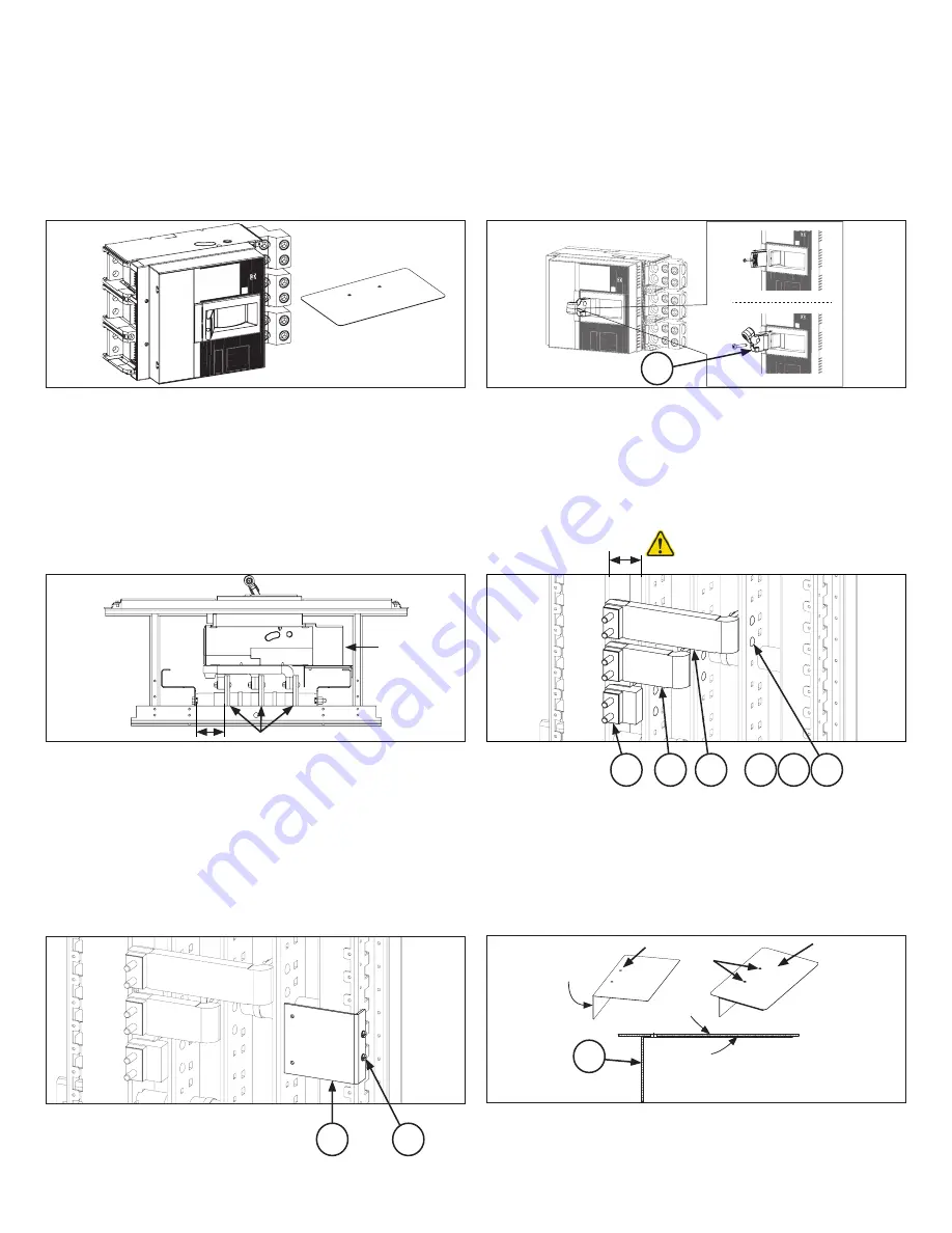
STEP 2
Remove flat cap and install foldable handle assembly (13) and
tighten the screw.
—
Figure 2. Install foldable handle assembly
STEP 4
Install the strap assemblies [10,11,12] with the corresponding
holes in the vertical bus, as shown in Figure 4. Fasten each strap
assembly loosely to the vertical bus with two carriage bolts [1],
Belleville washers [2] and nuts [3].
Main Bus
10
3
11
12
13
2
1
6x 6x 6x
2.75"
REF
LINE
LOAD
Cable entry
2.75" REF
Remove flat cap and screw
Install foldable handle assy
Figure 2a. Remove flat cap and screw
Figure 2b. Install foldable handle assembly
—
Figure 6. Prepare L-shaped barrier assembly
—
Figure 5. Installation of mounting bracket
STEP 5
Install the breaker mounting bracket [4] to the panel side rail with
thread forming screws [5], torque the screws to 35 lb- in. Refer
figure 5.
STEP 6
Prepare L-shaped barrier assembly. Fold L shaped barrier (8) as
shown in figure 6 and fix the breaker isolation base plate (sup
-
plied with breaker kit) to the adhesive surface of L shape barrier
(8) as shown in figure 6.
4
8
5
Folded
Breaker side
Adhesive side
Align holes
Breaker isolation
backplate
To mate with
mounting plate
2
STEP 1
Prepare the breaker, install required lugs and identify the re-
quired mounting and termination accessories from circuit
breaker kit. Refer to breaker instruction document for more infor-
mation.
—
Figure 1. Prepare the breaker
STEP 3
Find the side of the panel interior at which the dimension from
the face of nearest vertical bus to the inner face of the bus sup-
port rail is 2.75 inches, as illustrated in Figure 3.
—
Figure 3. Single branch, ABB XT7; Right side cable entry Assembly end view
—
Figure 4. Installation of link assy. A, B & C phase
2x


