—
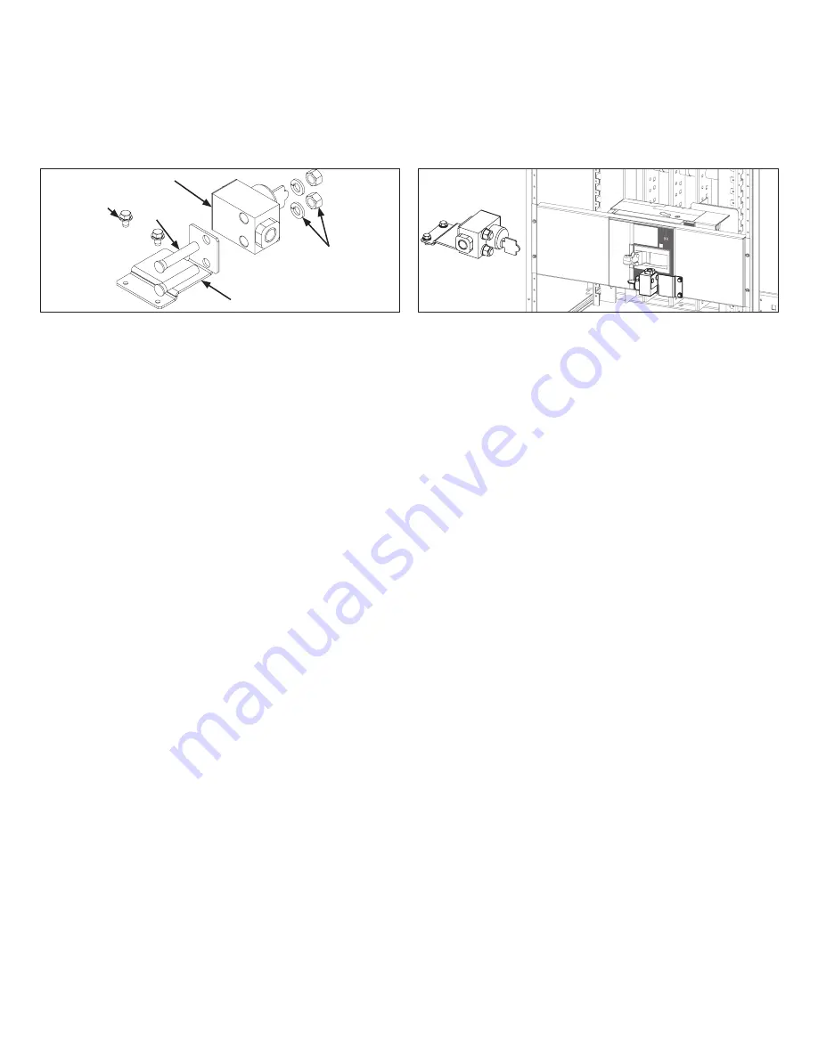
Figure 11b. Install the kirk lock
—
Figure 11a. Kirk lock mounting kit assembly
STEP 11 Continued
Install the kirk lock to the mounting plate 3/8 screw (2x), washer
(2x) and nut (2x) as shown in figure 11b. The assembled kirk lock
set to the installed on the panel XT7 filler plate with Thread form-
ing screw (2x) as shown in orientation in figure 11b.
STEP 11: Optional - Kirk lock mounting kit assembly
Pre-assemble Kirk lock mounting kit assembly as shown in figure
11a.
Note: Kirk-lock is not included in the kit. Re-use Kirk lock from
panel.
XT7 Kirk mounting plate
3/8 Nut and Washer
2x
Kirk lock block with key
Screw 3/8-16X
2x
2.00
2x
Thread forming
screw #10-32
D
o
cu
m
en
ta
ti
o
n N
u
m
b
er
: D
E
T 1
0
5
4
4
—
ABB Inc.
305 Gregson Drive
Cary, NC 27511
—
We reserve the right to make technical
changes or modify the contents of this doc-
ument without prior notice. With regard to
purchase orders, the agreed particulars
shall prevail. ABB AG does not accept any re-
sponsibility whatsoever for potential errors
or possible lack of information in this docu-
ment.
abb.com
We reserve all rights in this document and in
the subject matter and illustrations con-
tained therein. Any reproduction, disclosure
to third parties or utilization of its contents
– in whole or in parts – is forbidden without
prior written consent of ABB AG. Copy-
right© 2019 ABB
All rights reserved
Disclaimer :
These instructions do not cover all details or variations in equipment nor do they provide for every possible contingency that may be met in connection with installation, operation
or maintenance. Should further information be desired or should particular problems arise that are not covered sufficiently for the purchaser's purposes, the matter should be referred to the
ABB Company.
GE logo is licensed by General
Electric Company to ABB


