6–94
345 TRANSFORMER PROTECTION SYSTEM – INSTRUCTION MANUAL
S3 PROTECTION
CHAPTER 6: SETPOINTS
GND TOC1(2) CURVE
Range: ANSI Extremely/Very/Moderately/Normally Inverse, Definite Time IEC Curve A/B/
C and Short Inverse IAC Extremely/Very/Inverse/Short User Curve, FlexCurve A, FlexCurve
B
Default: Extremely Inverse
This setting sets the shape of the selected overcurrent inverse curve. If none of the
standard curve shapes is appropriate, a custom User curve, or FlexCurve can be
created. Refer to the User Curve and FlexCurve setup for more details about their
configuration and usage.
GND TOC1(2) TDM
Range: 0.50 to 20.00 in steps of 0.01
Default: 1.00
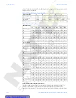
This setting provides the selection of the Time Dial Multiplier, using which the times from
the inverse curve are modified. For example if an ANSI Extremely Inverse curve is
selected with TDM = 2, and the fault current was 5 times greater than the PKP level, the
operation of the element will not occur before 2.59s has elapsed from the time of pickup.
GND TOC1(2) RESET
Range: Instantaneous, Linear
Default: Instantaneous
This setting provides for the selection of either an Instantaneous or a Linear reset time. If
Instantaneous reset is selected, the ground TOC element will reset instantaneously
providing the current drops below 97-98% below the Ground TOC PKP level, before the
time for operation is reached. When Linear reset is selected, the time to reset is
calculated based on the following linear equation:
Eq. 17
where:
T
RESET
- reset time in seconds;
E
- energy capacity reached (per unit);
M
- curve multiplier;
C
R
- characteristic constant (5 for ANSI, IAC, Definite Time, User Curve and FlexcurvesTM;
8 for IEC curves).
RLY1 TRIP W1 BKR and RLY2 TRIP W2 BKR
Range: Do not operate, Operate
Default: Do not operate
The menu for the two trip output relays - RLY1 TRIP W1 BKR and RLY2 TRIP W2 BKR - is
only available if the
Trip
setting is selected as a function for the Ground TOC element.
Either one, or both trip output relays can be selected to operate upon Ground TOC
operation.
NOTE
NOTE:
The "RLY1 TRIP W1 BKR" and "RLY2 TRIP W2 BKR" setpoints will be displayed on the OC
menu regardless of the selected OC function. These output relays will not operate if
either
Alarm
or
Latched Alarm
is selected as an OC function, regardless of the Operate/
Do Not Operate value selected. The output relays are operational only if the OC function
is selected as
Trip
.
OUTPUT RELAY 3 to 6
Range: Do not operate, Operate
Default: Do not operate
Any or all of the output relays 3 to 6 can be selected to operate upon ground TOC
operation. The selection of relay outputs operation is available no matter whether the
Latched Alarm
,
Alarm
, or
Trip
function is selected.


