SuperBus 2000 2-Amp Power Supply
Installation Instructions
2
permitted by the National Electrical Code ANSI/NFPA 70.
Wire that extends beyond the cable jacket must be
separated from all other conductors by a minimum of 0.25
in. or by a nonconductive barrier.
OR
(B) Class 2, Class 3, and power-limited fire alarm circuit
conductors must be installed as Class 1 or higher circuits.
Mounting inside panel cabinet
1.
Unplug the panel AC power transformer and disconnect the
backup battery.
2.
Install the support standoffs (included with panel) at the
panel locations shown in Figure 3.
Figure 3.
Installing panel support standoffs
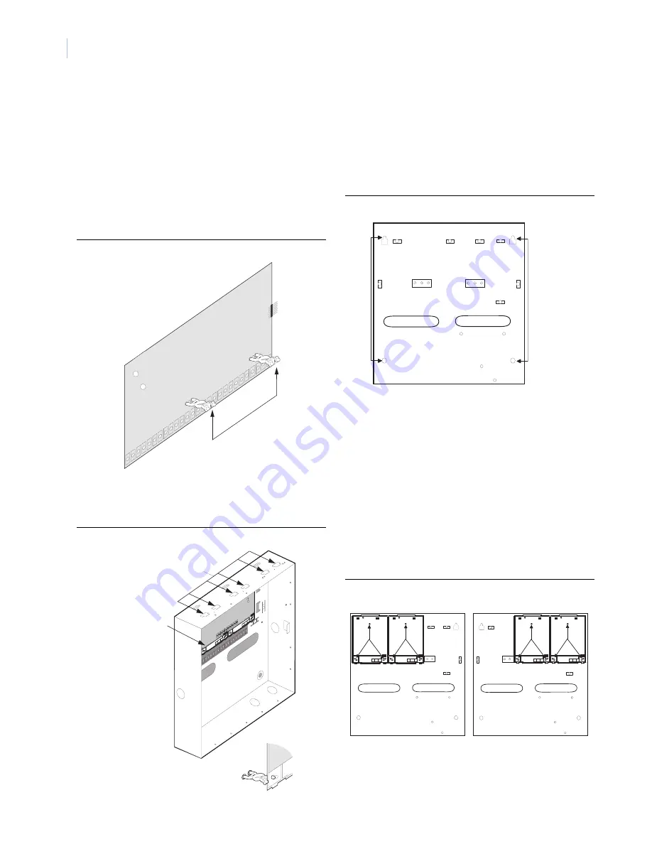
3.
Slide the top of the backplates onto the left and center
module mounting clips on the panel cabinet (Figure 4), then
snap the backplates on to the support standoffs (Detail in
Figure 4).
Figure 4.
Mounting power supply inside panel cabinet
Mounting inside Concord residential enclosure
Note:
This module is UL listed as a subassembly and must be
mounted in the same enclosure as the Concord 4 in UL
systems.
1.
Unplug the panel AC power transformer and disconnect the
backup battery.
2.
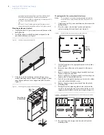
Place the cabinet at the desired location and mark the
cabinet mounting holes and knockouts (Figure 5).
Figure 5.
Residential enclosure mounting holes and knockouts
3.
Drill holes and insert the appropriate anchors where studs
are not present.
4.
Run wires from all devices to be powered, to the power
supply.
5.
Run a 4-conductor, 22-gauge or larger stranded wire from
the power supply to the panel.
6.
Run a 2-conductor, 18-gauge stranded wire from the power
supply to the AC transformer location.
7.
Feed all wires through the knockouts and secure the cabinet
to the wall with the included screws.
8.
Remove the power supply circuit board from the plastic
mounting plates.
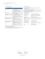
9.
Position the plastic mounting plates in the cabinet on the
top-left or top-right side and secure them with the six self-
tapping screws included with the power supply (Figure 6).
Figure 6.
Power supply mounting positions in residential enclosure (arrows
indicate screw locations)
10. Re-install the power supply circuit board on the plastic
mounting plates.
Mounting
Clips
Power Supply
on Backplates
Detail
Knockout
Knockout
Cabinet
Mounting
Holes (4)


