4-8
T35 Transformer Protection System
GE Multilin
4.2 EXTENDED ENERVISTA UR SETUP FEATURES
4 HUMAN INTERFACES
4
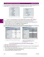
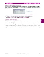
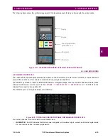
Viewing the settings in template mode also modifies the settings tree, showing only the settings categories that contain
editable settings. The effect of applying the template to a typical settings tree view is shown below.
Figure 4–5: APPLYING TEMPLATES VIA THE VIEW IN TEMPLATE MODE SETTINGS COMMAND
Use the following procedure to display settings available for editing and settings locked by the template.
1.
Select an installed device or a settings file from the tree menu on the left of the EnerVista UR Setup main screen.
2.
Apply the template by selecting the
Template Mode > View All Settings
option.
3.
Enter the template password then click
OK
to apply the template.
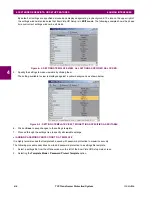
Once the template has been applied, users are limited to edit the settings specified by the template, but all settings are
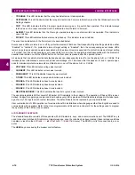
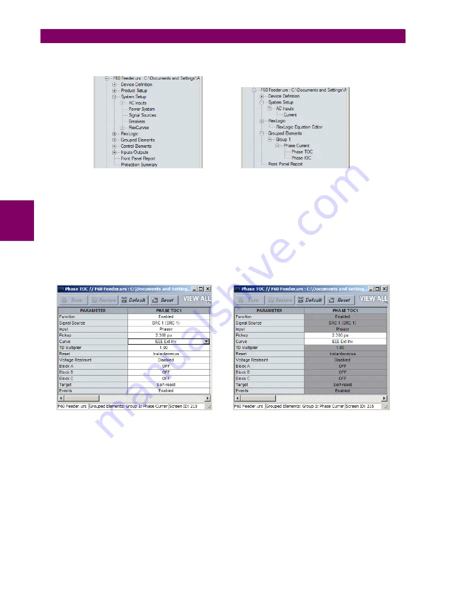
shown. The effect of applying the template to the phase time overcurrent settings is shown below.
Figure 4–6: APPLYING TEMPLATES VIA THE VIEW ALL SETTINGS COMMAND
e) REMOVING THE SETTINGS TEMPLATE
It can be necessary at some point to remove a settings template. Once a template is removed, it cannot be reapplied and it
is necessary to define a new settings template.
1.
Select an installed device or settings file from the tree menu on the left of the EnerVista UR Setup main screen.
2.
Select the
Template Mode > Remove Settings Template
option.
3.
Enter the template password and click
OK
to continue.
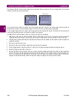
Typical settings tree view without template applied.
Typical settings tree view with template applied via
the
command.
Template Mode > View In Template Mode
842860A1.CDR
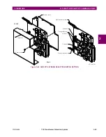
Phase time overcurrent settings window without template applied.
Phase time overcurrent window with template applied via
the
command.
The template specifies that only the
and
settings be available.
Template Mode > View All Settings
Pickup
Curve
842859A1.CDR
Summary of Contents for T35 UR Series
Page 10: ...x T35 Transformer Protection System GE Multilin TABLE OF CONTENTS ...
Page 48: ...2 18 T35 Transformer Protection System GE Multilin 2 2 SPECIFICATIONS 2 PRODUCT DESCRIPTION 2 ...
Page 314: ...5 192 T35 Transformer Protection System GE Multilin 5 10 TESTING 5 SETTINGS 5 ...
Page 338: ...6 24 T35 Transformer Protection System GE Multilin 6 5 PRODUCT INFORMATION 6 ACTUAL VALUES 6 ...
Page 350: ...7 12 T35 Transformer Protection System GE Multilin 7 2 TARGETS 7 COMMANDS AND TARGETS 7 ...
Page 366: ...8 16 T35 Transformer Protection System GE Multilin 8 2 CYBERSENTRY 8 SECURITY 8 ...
Page 406: ...A 14 T35 Transformer Protection System GE Multilin A 1 PARAMETER LISTS APPENDIX A A ...
Page 540: ...D 10 T35 Transformer Protection System GE Multilin D 1 IEC 60870 5 104 PROTOCOL APPENDIX D D ...
Page 552: ...E 12 T35 Transformer Protection System GE Multilin E 2 DNP POINT LISTS APPENDIX E E ...
Page 560: ...F 8 T35 Transformer Protection System GE Multilin F 3 WARRANTY APPENDIX F F ...

