GE Multilin
T35 Transformer Protection System
5-149
5 SETTINGS
5.7 CONTROL ELEMENTS
5
•
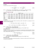
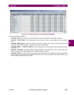
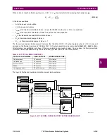
SELECTOR 1 TIME-OUT:
This setting defines the time-out period for the selector. This value is used by the relay in
the following two ways. When the
SELECTOR STEP-UP MODE
is “Time-out”, the setting specifies the required period of
inactivity of the control input after which the pre-selected position is automatically applied. When the
SELECTOR STEP-
UP MODE
is “Acknowledge”, the setting specifies the period of time for the acknowledging input to appear. The timer is
re-started by any activity of the control input. The acknowledging input must come before the
SELECTOR 1 TIME-OUT
timer expires; otherwise, the change will not take place and an alarm will be set.
•
SELECTOR 1 STEP-UP
: This setting specifies a control input for the selector switch. The switch is shifted to a new
position at each rising edge of this signal. The position changes incrementally, wrapping up from the last (
SELECTOR 1
FULL RANGE
) to the first (position 1). Consecutive pulses of this control operand must not occur faster than every
50 ms. After each rising edge of the assigned operand, the time-out timer is restarted and the
SELECTOR SWITCH 1:
POS Z CHNG INITIATED
target message is displayed, where
Z
the pre-selected position. The message is displayed for
the time specified by the
FLASH MESSAGE TIME
setting. The pre-selected position is applied after the selector times out
(“Time-out” mode), or when the acknowledging signal appears before the element times out (“Acknowledge” mode).
When the new position is applied, the relay displays the
SELECTOR SWITCH 1: POSITION Z IN USE
message. Typically,
a user-programmable pushbutton is configured as the stepping up control input.
•
SELECTOR 1 STEP-UP MODE
: This setting defines the selector mode of operation. When set to “Time-out”, the
selector will change its position after a pre-defined period of inactivity at the control input. The change is automatic and
does not require any explicit confirmation of the intent to change the selector's position. When set to “Acknowledge”,
the selector will change its position only after the intent is confirmed through a separate acknowledging signal. If the
acknowledging signal does not appear within a pre-defined period of time, the selector does not accept the change
and an alarm is established by setting the
SELECTOR STP ALARM
output FlexLogic operand for 3 seconds.
•
SELECTOR 1 ACK
: This setting specifies an acknowledging input for the stepping up control input. The pre-selected
position is applied on the rising edge of the assigned operand. This setting is active only under “Acknowledge” mode of
operation. The acknowledging signal must appear within the time defined by the
SELECTOR 1 TIME-OUT
setting after the
last activity of the control input. A user-programmable pushbutton is typically configured as the acknowledging input.
•
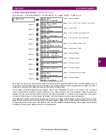
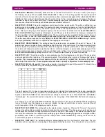
SELECTOR 1 3BIT A0, A1, and A2
: These settings specify a three-bit control input of the selector. The three-bit con-
trol word pre-selects the position using the following encoding convention:
The “rest” position (0, 0, 0) does not generate an action and is intended for situations when the device generating the
three-bit control word is having a problem. When
SELECTOR 1 3BIT MODE
is “Time-out”, the pre-selected position is
applied in
SELECTOR 1 TIME-OUT
seconds after the last activity of the three-bit input. When
SELECTOR 1 3BIT MODE
is
“Acknowledge”, the pre-selected position is applied on the rising edge of the
SELECTOR 1 3BIT ACK
acknowledging
input.
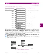
The stepping up control input (
SELECTOR 1 STEP-UP
) and the three-bit control inputs (
SELECTOR 1 3BIT A0
through
A2
)
lock-out mutually: once the stepping up sequence is initiated, the three-bit control input is inactive; once the three-bit
control sequence is initiated, the stepping up input is inactive.
•
SELECTOR 1 3BIT MODE
: This setting defines the selector mode of operation. When set to “Time-out”, the selector
changes its position after a pre-defined period of inactivity at the control input. The change is automatic and does not
require explicit confirmation to change the selector position. When set to “Acknowledge”, the selector changes its posi-
tion only after confirmation via a separate acknowledging signal. If the acknowledging signal does not appear within a
pre-defined period of time, the selector rejects the change and an alarm established by invoking the
SELECTOR BIT
ALARM
FlexLogic operand for 3 seconds.
•
SELECTOR 1 3BIT ACK
: This setting specifies an acknowledging input for the three-bit control input. The pre-
selected position is applied on the rising edge of the assigned FlexLogic operand. This setting is active only under the
A2
A1
A0
POSITION
0
0
0
rest
0
0
1
1
0
1
0
2
0
1
1
3
1
0
0
4
1
0
1
5
1
1
0
6
1
1
1
7
Summary of Contents for T35 UR Series
Page 10: ...x T35 Transformer Protection System GE Multilin TABLE OF CONTENTS ...
Page 48: ...2 18 T35 Transformer Protection System GE Multilin 2 2 SPECIFICATIONS 2 PRODUCT DESCRIPTION 2 ...
Page 314: ...5 192 T35 Transformer Protection System GE Multilin 5 10 TESTING 5 SETTINGS 5 ...
Page 338: ...6 24 T35 Transformer Protection System GE Multilin 6 5 PRODUCT INFORMATION 6 ACTUAL VALUES 6 ...
Page 350: ...7 12 T35 Transformer Protection System GE Multilin 7 2 TARGETS 7 COMMANDS AND TARGETS 7 ...
Page 366: ...8 16 T35 Transformer Protection System GE Multilin 8 2 CYBERSENTRY 8 SECURITY 8 ...
Page 406: ...A 14 T35 Transformer Protection System GE Multilin A 1 PARAMETER LISTS APPENDIX A A ...
Page 540: ...D 10 T35 Transformer Protection System GE Multilin D 1 IEC 60870 5 104 PROTOCOL APPENDIX D D ...
Page 552: ...E 12 T35 Transformer Protection System GE Multilin E 2 DNP POINT LISTS APPENDIX E E ...
Page 560: ...F 8 T35 Transformer Protection System GE Multilin F 3 WARRANTY APPENDIX F F ...

