GE Multilin
T35 Transformer Protection System
6-19
6 ACTUAL VALUES
6.3 METERING
6
6.3.6 IEC 61580 GOOSE ANALOG VALUES
PATH: ACTUAL VALUES
METERING
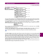
IEC 61850 GOOSE ANALOGS
The T35 Transformer Protection System is provided with optional IEC 61850 communications capability.
This feature is specified as a software option at the time of ordering. Refer to the
Ordering
section of chap-
ter 2 for additional details.
The IEC 61850 GGIO3 analog input data points are displayed in this menu. The GGIO3 analog data values are received
via IEC 61850 GOOSE messages sent from other devices.
6.3.7 TRANSDUCER INPUTS/OUTPUTS
PATH: ACTUAL VALUES
METERING
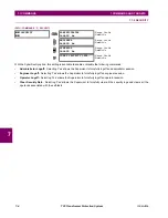
TRANSDUCER I/O DCMA INPUTS
DCMA INPUT xx
Actual values for each DCmA input channel that is enabled are displayed with the top line as the programmed channel ID
and the bottom line as the value followed by the programmed units.
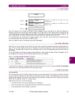
Table 6–2: FLEXELEMENT BASE UNITS
DCmA
BASE = maximum value of the
DCMA INPUT MAX
setting for the two transducers configured
under the +IN and –IN inputs.
FREQUENCY
f
BASE
= 1 Hz
PHASE ANGLE
ϕ
BASE
= 360 degrees (see the UR angle referencing convention)
POWER FACTOR
PF
BASE
= 1.00
RTDs
BASE = 100°C
SOURCE CURRENT
I
BASE
= maximum nominal primary RMS value of the +IN and –IN inputs
SOURCE POWER
P
BASE
= maximum value of V
BASE
×
I
BASE
for the +IN and –IN inputs
SOURCE VOLTAGE
V
BASE
= maximum nominal primary RMS value of the +IN and –IN inputs
XFMR DIFFERENTIAL CURRENT
(Xfmr Iad, Ibd, and Icd Mag)
I
BASE
= maximum primary RMS value of the +IN and -IN inputs
(CT primary for source currents, and transformer reference primary current for transformer
differential currents)
XFMR DIFFERENTIAL
HARMONIC CONTENT
(Xfmr Harm2 Iad, Ibd, and Icd Mag)
(Xfmr Harm5 Iad, Ibd, and Icd Mag)
BASE = 100%
XFMR RESTRAINING CURRENT
(Xfmr Iar, Ibr, and Icr Mag)
I
BASE
= maximum primary RMS value of the +IN and -IN inputs
(CT primary for source currents, and transformer reference primary current for transformer
differential currents)
IEC 61850
GOOSE ANALOGS
ANALOG INPUT
1
0.000
MESSAGE
ANALOG INPUT
2
0.000
MESSAGE
ANALOG INPUT
3
0.000
↓
MESSAGE
ANALOG INPUT 32
0.000
DCMA INPUT xx
DCMA INPUT xx
0.000 mA
Summary of Contents for T35 UR Series
Page 10: ...x T35 Transformer Protection System GE Multilin TABLE OF CONTENTS ...
Page 48: ...2 18 T35 Transformer Protection System GE Multilin 2 2 SPECIFICATIONS 2 PRODUCT DESCRIPTION 2 ...
Page 314: ...5 192 T35 Transformer Protection System GE Multilin 5 10 TESTING 5 SETTINGS 5 ...
Page 338: ...6 24 T35 Transformer Protection System GE Multilin 6 5 PRODUCT INFORMATION 6 ACTUAL VALUES 6 ...
Page 350: ...7 12 T35 Transformer Protection System GE Multilin 7 2 TARGETS 7 COMMANDS AND TARGETS 7 ...
Page 366: ...8 16 T35 Transformer Protection System GE Multilin 8 2 CYBERSENTRY 8 SECURITY 8 ...
Page 406: ...A 14 T35 Transformer Protection System GE Multilin A 1 PARAMETER LISTS APPENDIX A A ...
Page 540: ...D 10 T35 Transformer Protection System GE Multilin D 1 IEC 60870 5 104 PROTOCOL APPENDIX D D ...
Page 552: ...E 12 T35 Transformer Protection System GE Multilin E 2 DNP POINT LISTS APPENDIX E E ...
Page 560: ...F 8 T35 Transformer Protection System GE Multilin F 3 WARRANTY APPENDIX F F ...


