B-24
T35 Transformer Protection System
GE Multilin
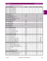
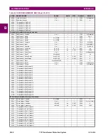
B.4 MEMORY MAPPING
APPENDIX B
B
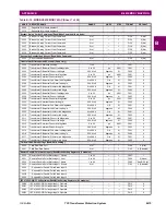
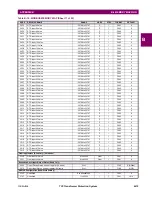
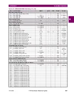
3FBE
Attached Filed Unit 1 Port Number
---
---
1
F001
0
3FBF
Attached Field Unit 1 Type
0 to 3
---
1
F243
0 (CC-05)
3FC0
Field Unit 1 Status
0 to 4
---
1
F262
0 (Disabled)
3FC1
...Repeated for Field Unit 2
3FCA
...Repeated for Field Unit 3
3FD3
...Repeated for Field Unit 4
3FDC
...Repeated for Field Unit 5
3FE5
...Repeated for Field Unit 6
3FEE
...Repeated for Field Unit 7
3FF7
...Repeated for Field Unit 8
Passwords (Read/Write Command)
4000
Command Password Setting
0 to 4294967295
---
1
F202
(none)
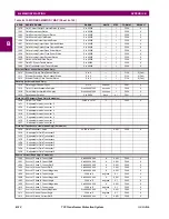
Passwords (Read/Write Setting)
400A
Setting Password Setting
0 to 4294967295
---
1
F202
(none)
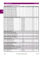
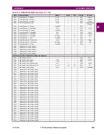
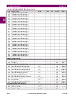
Passwords (Read/Write)
4014
Command Password Entry
0 to 4294967295
---
1
F202
(none)
401E
Setting Password Entry
0 to 4294967295
---
1
F202
(none)
Passwords (Read Only)
4028
Command Password Status
0 to 1
---
1
F102
0 (Disabled)
4029
Setting Password Status
0 to 1
---
1
F102
0 (Disabled)
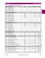
Passwords (Read/Write Setting)
402A
Command Password Access Timeout
5 to 480
min
1
F001
5
402B
Setting Password Access Timeout
5 to 480
min
1
F001
30
402C
Invalid Password Attempts (before lockout)
2 to 5
---
1
F001
3
402D
Password Lockout Duration
5 to 60
min
1
F001
5
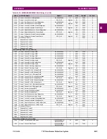
Passwords (Read/Write)
402E
Password Access Events
0 to 1
---
1
F102
0 (Disabled)
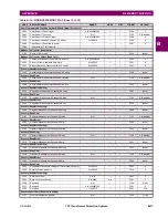
Passwords (Read/Write Setting)
402F
Local Setting Auth
1 to 4294967295
---
1
F300
1
4031
Remote Setting Auth
0 to 4294967295
---
1
F300
1
4033
Access Auth Timeout
5 to 480
min
1
F001
30
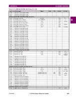
User Display Invoke (Read/Write Setting)
4040
Invoke and Scroll Through User Display Menu Operand
0 to 4294967295
---
1
F300
0
LED Test (Read/Write Setting)
4048
LED Test Function
0 to 1
---
1
F102
0 (Disabled)
4049
LED Test Control
0 to 4294967295
---
1
F300
0
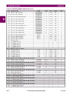
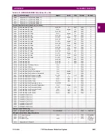
Preferences (Read/Write Setting)
404F
Language
0 to 4
---
1
F531
0 (English)
4050
Flash Message Time
0.5 to 10
s
0.1
F001
10
4051
Default Message Timeout
10 to 900
s
1
F001
300
4052
Default Message Intensity
0 to 3
---
1
F101
0 (25%)
4053
Screen Saver Feature
0 to 1
---
1
F102
0 (Disabled)
4054
Screen Saver Wait Time
1 to 65535
min
1
F001
30
4055
Current Cutoff Level
0.002 to 0.02
pu
0.001
F001
20
4056
Voltage Cutoff Level
0.1 to 1
V
0.1
F001
10
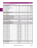
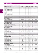
Communications (Read/Write Setting)
407D
COM2 Selection
0 to 3
---
1
F601
0 (RS485)
407E
COM1 Minimum Response Time
0 to 1000
ms
10
F001
0
407F
COM2 Minimum Response Time
0 to 1000
ms
10
F001
0
4080
Modbus Slave Address
1 to 254
---
1
F001
254
4083
RS485 Com1 Baud Rate
0 to 11
---
1
F112
8 (115200)
4084
RS485 Com1 Parity
0 to 2
---
1
F113
0 (None)
4085
RS485 Com2 Baud Rate
0 to 11
---
1
F112
8 (115200)
4086
RS485 Com2 Parity
0 to 2
---
1
F113
0 (None)
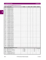
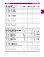
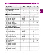
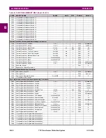
Table B–10: MODBUS MEMORY MAP (Sheet 16 of 52)
ADDR
REGISTER NAME
RANGE
UNITS
STEP
FORMAT
DEFAULT
Summary of Contents for T35 UR Series
Page 10: ...x T35 Transformer Protection System GE Multilin TABLE OF CONTENTS ...
Page 48: ...2 18 T35 Transformer Protection System GE Multilin 2 2 SPECIFICATIONS 2 PRODUCT DESCRIPTION 2 ...
Page 314: ...5 192 T35 Transformer Protection System GE Multilin 5 10 TESTING 5 SETTINGS 5 ...
Page 338: ...6 24 T35 Transformer Protection System GE Multilin 6 5 PRODUCT INFORMATION 6 ACTUAL VALUES 6 ...
Page 350: ...7 12 T35 Transformer Protection System GE Multilin 7 2 TARGETS 7 COMMANDS AND TARGETS 7 ...
Page 366: ...8 16 T35 Transformer Protection System GE Multilin 8 2 CYBERSENTRY 8 SECURITY 8 ...
Page 406: ...A 14 T35 Transformer Protection System GE Multilin A 1 PARAMETER LISTS APPENDIX A A ...
Page 540: ...D 10 T35 Transformer Protection System GE Multilin D 1 IEC 60870 5 104 PROTOCOL APPENDIX D D ...
Page 552: ...E 12 T35 Transformer Protection System GE Multilin E 2 DNP POINT LISTS APPENDIX E E ...
Page 560: ...F 8 T35 Transformer Protection System GE Multilin F 3 WARRANTY APPENDIX F F ...


