GE Multilin
T35 Transformer Protection System
9-3
9 COMMISSIONING
9.2 DIFFERENTIAL CHARACTERISTIC TEST EXAMPLES
9
9.2DIFFERENTIAL CHARACTERISTIC TEST EXAMPLES
9.2.1 INTRODUCTION
The T35 commissioning tests are based on secondary current injections, where two or three individually adjustable cur-
rents are required. The differential protection compares the magnitudes of the varying HV and LV currents in real time.
Therefore, the test set currents and their angles must be an exact replica of the HV and LV currents and angles shown on
the diagrams, along with the correct CT polarity and orientation.
Ensure that the thermal rating of the relay current inputs is not exceeded. Stopping the injection of the currents to the relay
by using contact outputs triggered by protection operation can prevent this from occurring.
Due to the complexity of the mathematics defining the operating characteristic of the region between Breakpoint 1 and 2,
the use of a factory-supplied Microsoft Excel simulation utility is highly recommended. This utility indicates graphically
whether the relay should operate, based on the settings and winding current injection. This allows the tester to define and
confirm various points on the operating characteristic. The spreadsheet can be found at GE Multilin website (look in the
support documents for the product).
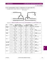
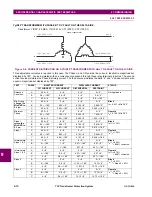
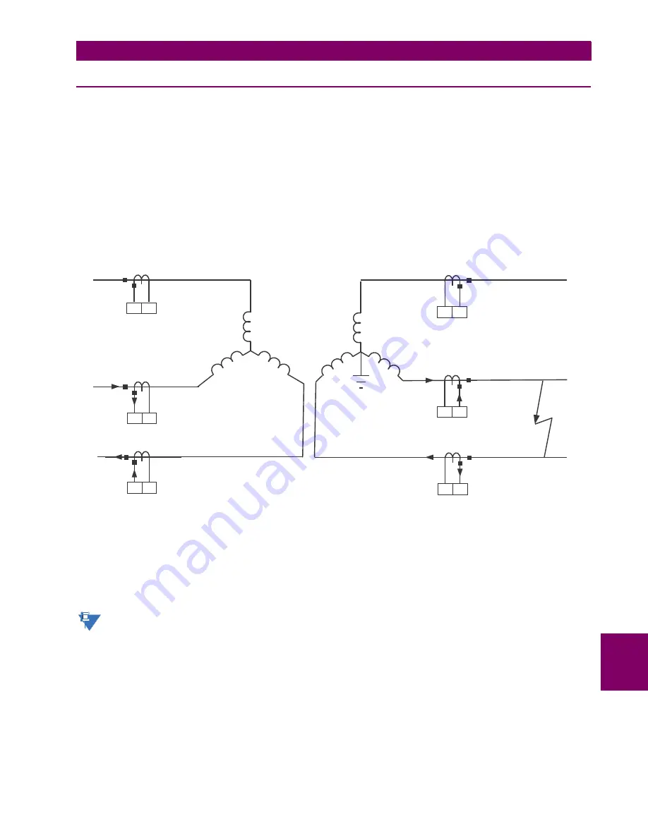
Figure 9–2: CURRENT DISTRIBUTION ON A Y/YG0° TRANSFORMER WITH b-c FAULT ON LV SIDE
Consider the above system, which illustrates the importance of CT orientation, polarity and relay connection. These factors
will also apply when performing the tests outlined in the next examples.
The transformer high voltage (HV) and low voltage (LV) side fault currents, and angles are all related. More specifically, the
HV and LV primary fault currents are displaced by 180°. The CT polarity marks point away from the protected zone and are
connected to the
~a
terminals of the relay. The displayed current is what is reported by the relay.
The
~a
and
~b
terminal identifications are illustrative only. Refer to CT/VT Modules section in Chapter 3 for specific
terminal identification.
828736A1.CDR
IC = 0.866
–270° pu
∠
BC Fault
~c
~b
IA = 0 pu
~c
~b
IB = 0.866
–90° pu
∠
~c
~b
~c
~b
Ia = 0 pu
~c
~b
Ic = 0.866
–90° pu
∠
~c
~b
Ib = 0.866
–270° pu
∠
Y/y0°
Transformer
NOTE
Summary of Contents for T35 UR Series
Page 10: ...x T35 Transformer Protection System GE Multilin TABLE OF CONTENTS ...
Page 48: ...2 18 T35 Transformer Protection System GE Multilin 2 2 SPECIFICATIONS 2 PRODUCT DESCRIPTION 2 ...
Page 314: ...5 192 T35 Transformer Protection System GE Multilin 5 10 TESTING 5 SETTINGS 5 ...
Page 338: ...6 24 T35 Transformer Protection System GE Multilin 6 5 PRODUCT INFORMATION 6 ACTUAL VALUES 6 ...
Page 350: ...7 12 T35 Transformer Protection System GE Multilin 7 2 TARGETS 7 COMMANDS AND TARGETS 7 ...
Page 366: ...8 16 T35 Transformer Protection System GE Multilin 8 2 CYBERSENTRY 8 SECURITY 8 ...
Page 406: ...A 14 T35 Transformer Protection System GE Multilin A 1 PARAMETER LISTS APPENDIX A A ...
Page 540: ...D 10 T35 Transformer Protection System GE Multilin D 1 IEC 60870 5 104 PROTOCOL APPENDIX D D ...
Page 552: ...E 12 T35 Transformer Protection System GE Multilin E 2 DNP POINT LISTS APPENDIX E E ...
Page 560: ...F 8 T35 Transformer Protection System GE Multilin F 3 WARRANTY APPENDIX F F ...

