background image

Measure and cut Tetra LED 

strip to the appropriate length 

for each letter. Cuts can be 

made between any of the 

modules.

2

Use the double stick tape or 

electrical grade RTV silicone 

to fix LED module within the 

channel letter.

4

Drill a 1/4-inch (6.4 mm) 

hole near the LED strip and 

grommet the hole for supply 

wire access.

5

6

Remove all the debris from the 

inside of the channel letter and 

replace the sign face. 

NOTE:

 For halo-lit applications LED modules should be mounted on UL 

recognized clear acrylic or polycarbonate. The light output from the LED 

system should be directed back into the sign enclosure. This will allow for 

uniform backlighting of the sign and will provide simple mounting.

Before you begin, clean 

surfaces and remove all debris 

from the inside of the channel 

letter.Clean the surfaces with 

a 50:50 mixture of isopropyl 

alcohol (IPA) and water and let 

dry.

1

Layout Modules

Remove tape backing and stick 

LED modules into place. When 

using tape apply approximately 

15 psi pressure on the module 

(avoid the lens dome surface) for 

5 seconds, full bonding strength 

after 24 hours. Continue until you 

have reached the end of the strip.

3

Do not 

press lens

Electrical Connections

NOTE: 

Do not use connectors pre-filled with silicone grease/mineral base protective grease or use silicone grease to seal connections.

Cap wires

Optional:

 Cut wires flush

Must cap all exposed wires with appropriate wire 

connectors and seal with electrical grade RTV silicone. 

Optional: 

Cut wires flush to the module and seal with 

electrical grade RTV silicone.

2

Connect LED strips using in-line (IDC) connectors or 

twist-on wire connectors.
NOTE: 

Seal all connections in wet locations with 

electrical grade RTV silicone.

1

Red stripe (+)

White (-)

Seal all connections in wet locations 

with electrical grade RTV silicone

3

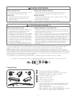
Summary of Contents for Tetra miniMAX MS

Page 1: ...s instrucciones de instalación y la información sobre seguridad puede encontrarse en la siguiente ubicación https products currentbyge com eu ET Eestikeelse paigaldusjuhendi ja ohutusnñuded leiate aadressilt https products currentbyge com eu FI Asennusohjeiden ja turvallisuustietojen suomenkielinen versio löytyy seuraavasta paikasta https products currentbyge com eu FR La version française des ins...

Page 2: ...eut impliquer le perçage ou le poinçonnage de trous dans la structure du panneau Vérifiez le câblage et les composants inclus pour éviter d endommager le câblage et les composants électriques Ne pas faire ou modifier les trous ouverts dans une enceinte de câblage ou de composants électriques pendant l installation de cet équipement de remplacement DEL This device complies with part 15 of the FCC R...

Page 3: ...urfaces with a 50 50 mixture of isopropyl alcohol IPA and water and let dry 1 Layout Modules Remove tape backing and stick LED modules into place When using tape apply approximately 15 psi pressure on the module avoid the lens dome surface for 5 seconds full bonding strength after 24 hours Continue until you have reached the end of the strip 3 Do not press lens Electrical Connections NOTE Do not u...

Page 4: ...NOTE Follow all federal and local regulations when disposing of neon tubing fluorescent tubes transformers and ballasts 3 Existing Signs Only If removal of the existing lighting equipment eliminates the disconnect switch as required by applicable local state or country electrical codes a new disconnect switch must be installed 4 Existing Signs Only Repair and seal any unused openings in the electr...

Page 5: ... the supply wire at the point at which it is brought into the sign is to have a drip loop on the inside of the letter to keep water from collecting on the Tetra LED strip These products are not required to be enclosed or protected from weather Troubleshooting Symptom Solution All letters are OFF Check AC input connection and or check circuit breaker Check wire connection s at the Tetra LED System ...

Reviews: