background image

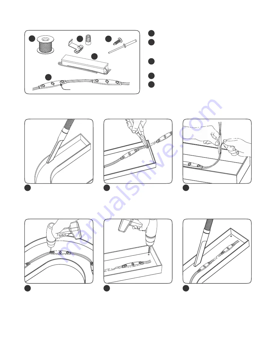
Components

1
2

UL approved 18 AWG supply wire (0.82 mm

2

)

UL approved 22-14 AWG twist-on wire connectors 
(0.33 - 2.08 mm

2

) or 18-14 AWG In-line/IDC 

connectors (0.82 - 2.08 mm

2

)

#6 or #8 (M3 or M4) screws, 1/8 inch (3.2 mm) rivets, 
or electronic grade silicone or equivalent

Tetra

®  

12 Volt Power Supply

Tetra

®  

Wet Location PowerMAX LED Modules

1

2

3

4

3

4
5

5

T

C

Measure Point

Layout Modules

1

2

3

Clean and remove all debris
from the inside of the channel 
letter before you begin.

Measure and cut Tetra

®  

LED

strip to the appropriate length 
for each letter. Cuts can be 
made between any of the 
modules.

Remove tape backing and
stick LED modules into place. 
Continue until you have 
reached the end of the strip.

4

5

6

Use rivets, screws, or silicone
to secure at least every fifth 
LED module within the channel 
letter. Use #6 (M3) or #8 (M4) 
pan headed metal screws,
1/8-inch (3.2 mm) rivets, or 
silicone.

Drill a

1/4”

(6.4 mm) hole near

the LED strip and grommet 
the hole for supply wire 
access.

Clean and remove all debris
from the inside of the channel 
letter. Replace sign face.

NOTE:

For halo-lit applications LED modules should be mounted on UL

recognized clear acrylic or polycarbonate. The light output from the LED 
system should be directed back into the sign enclosure. This will allow for 
uniform backlighting  of the sign and will provide simple mounting.

Summary of Contents for Tetra PowerMAX GEPM71-W1

Page 1: ...tion against harmful interference when the equipment is operated in a commercial environment This equipment generates uses and can radiate radio frequency energy and if not installed and used in accordance with the instruction manual may cause harmful interference to radio communications Operation of this equipment in a residential area is likely to cause harmful interference in which case the use...

Page 2: ...n any of the modules Remove tape backing and stick LED modules into place Continue until you have reached the end of the strip 4 5 6 Use rivets screws or silicone to secure at least every fifth LED module within the channel letter Use 6 M3 or 8 M4 pan headed metal screws 1 8 inch 3 2 mm rivets or silicone Drill a 1 4 6 4 mm hole near the LED strip and grommet the hole for supply wire access Clean ...

Page 3: ...onnect switch as required by applicable local state or country electrical codes a new disconnect switch must be installed Existing Signs Only Make sure the removal of lighting equipment does not compromise the integrity of the sign body i e water intrusion Fill in all holes 0 5 in 13 mm or smaller with the appropriate amount of rated caulk or sealant For holes greater than 0 5 in 13 mm use an alum...

Page 4: ...sign enclosure This will allow for uniform backlighting of the sign and will provide simple mounting for the Tetra LED system A best practice for the supply wire at the point at which it is brought into the sign is to have a drip loop on the inside of the letter to keep water from collecting on the Tetra LED strip These products are not required to be enclosed or protected from weather Specificati...

Reviews: