Critical Power
Modifications reserved
Page 20/92
GE_UPS_USM_TLE_SUL_M62_1M0_2US_V010.docx
User Manual
TLE Series 625 - 750 - 1000 UL S2
4.3.7
TLE Series 625 – 750 – 1000 with “IP Ring Bus” (option)
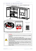
Maintenance of the TLE Series 625 – 750 - 1000 whit “IP RING BUS” option
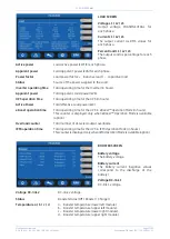
Fig. 4.3.7-1 TLE Series 625 – 750 – 1000 electronic bracket
Fig. 4.3.7-2 IP Ring Bus fuses
WARNING !
All maintenance and service works must be performed by GE SERVICE
PERSONNEL !
TLE Series 625 – 750 – 1000
with “IP Ring Bus” option:
In case of “IP Ring Bus” option be aware that external hazardous voltage can
be supplied from the IP cabinet (FU1, FU2, FU3 / Fig. 4.3.7-2) to the IM0278
(J19.10, J19.7, J19.4 / Fig. 4.3.7-1)
and to the connector XRB1 (Fig. 4.3.7-1) even
after UPS shut down.
To remove the hazardous voltages it is necessary to manually open the IP
cabinet fuses (FU1, FU2, FU3 / Fig. 4.3.7-2), checking the presence of any
voltage before working on the UPS.
Read carefully the documentation provided together with the external “IP
Ring Bus”
cabinet.
IP_Ring Bus_
TLES_1000
_S2_Electro
nic bracket
_01
Electronic bracket
EP
O
EP
O
- +
1
2
Q1
0 OFF
I ON
1-10-7-4
3-8-1-6
1-6-2-7-4-9
U
PS
O
ff (
N
O)
M
ain
te
nan
ce
(N
O
)
Rin
gI
nh
ib
ite
d (
N
O
)
Rin
g
- L
1
Rin
g
- L
2
Rin
g
- L
3
Ri
ng
- N
1
2 3 4
1
2 3 4 5 6 7 8 9
TLE Series 1000 UL S1
P2
P2
P3 + P18
J_SSM2
J9
J6 J7
J18
Option in added into Electronic Bracket
J23
J24
J7 J8
J18
IM279
IM278
J21
J20
J19
10 11 12
XRB2
XRB1
By
pa
ss
C
lo
se
d (G
N
D
)
By
pa
ss
C
lo
se
d (+
24
V)
Rin
gb
us
c
on
ne
ct
ed (
GN
D
)
Ri
ng
bu
s c
on
ne
ct
ed
(+24V
)
TLE Series Electronic Bracket
IM279
IM278
P2
P3
P1
XRB2
XRB1
IP Ring Bus cabinet
FIELD WIRES
FU3
1
2
BC
1
(I
PBU
SL
IMI
T:
C1
) %
FU2
1
2
BB1
(IP
BU
SL
IMI
T:
B1
) %
FU1
1
2
BA
1
(I
PBU
SL
IMI
T:
A1
) %


