Critical Power
Modifications reserved
Page 21/53
GE_UPS_ISG_TLE_SUL_40K_M15_1US_V010.docx
Installation Guide TLE Scalable Series 40 - 150 UL S1
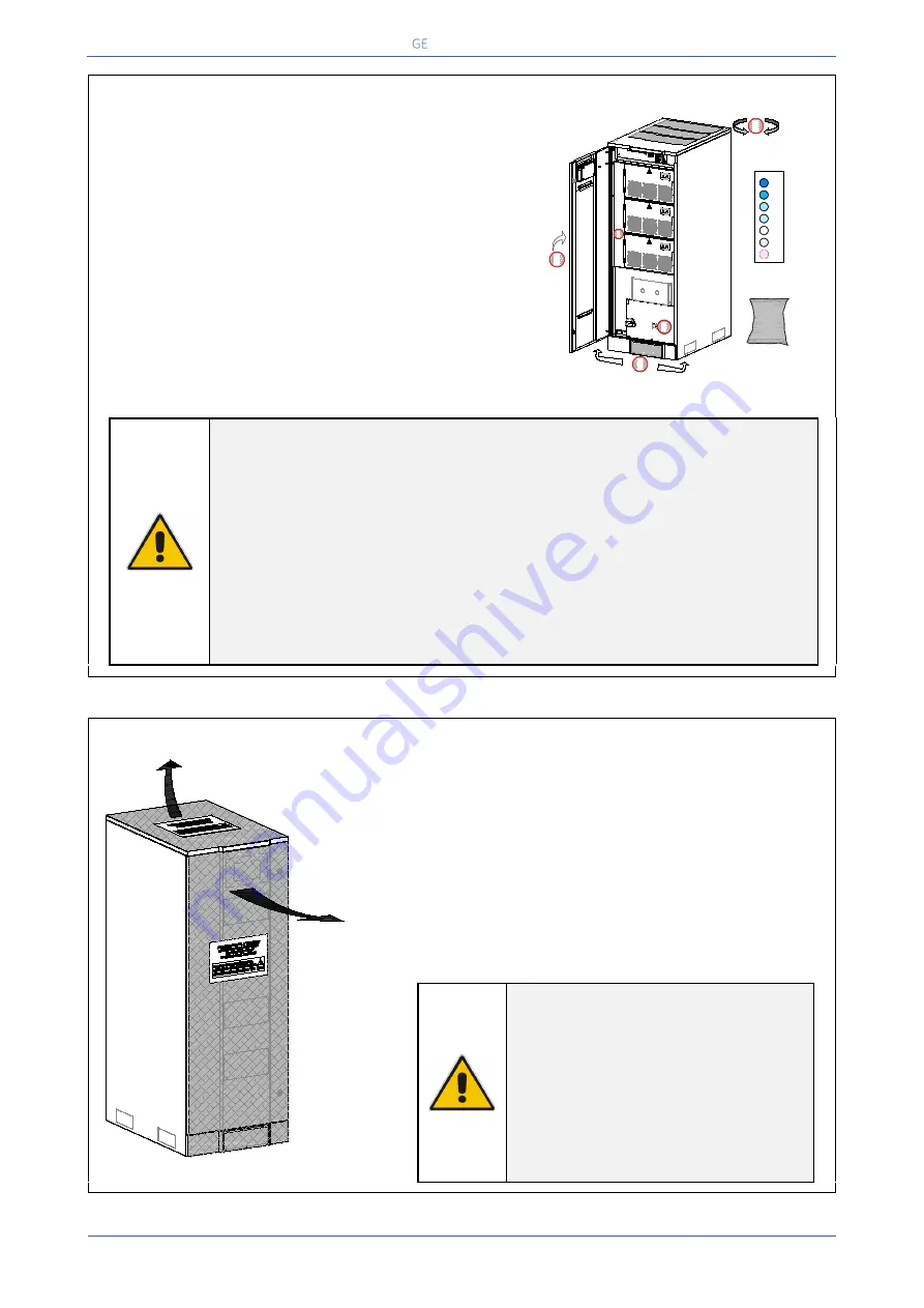
ANTI-HUMIDITY & CORROSION DEVICES
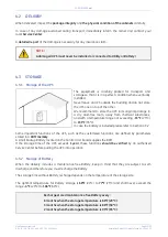
The package of the TLE Scalable Series 40 - 150
includes the “Anti-Humidity & Corrosion devices”
against the formation of humidity and corrosion
during the transportation and the storage of the UPS.
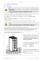
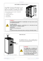
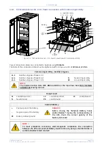
“Anti-Humidity & Corrosion devices” components:
A.
Humidity indicator
B.
Desiccant bag (2 pcs.)
C.
VCI foil base
D.
PE stretch foil
Fig. 4.6-3 Location of the “Anti-Humidity & Corrosion devices”
WARNING !
It’s MANDATORY TO REMOVE the “
Anti-Humidity & Corrosion devices”
during
the unpacking of the UPS!
Humidity indicator
Before removing the devices
“C - VCI foil base” & “D - PE stretch foil”
, check
the status of the
“A - Humidity indicator”
.
10% to 70%:
The UPS can be commissioned.
80%:
The UPS shall not be commissioned. Please contact your
“GE Service Center”
.
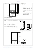
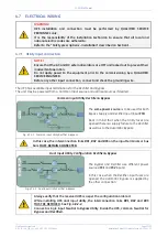
Fig. 4.6-4 Location of the “Protective Foil”
PROTECTIVE FOIL
TLE Scalable Series 40 - 150
is provided with a
“Protective Foil”
, on the roof and door/front panels, to
prevent material from falling into UPS.
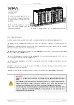
WARNING !
It’s MANDATORY TO REMOVE the
“Protective Foil”
but only just before
the first start-up of the UPS as
indicated in the appropriate label!
The removal of the
"PROTECTIVE
FOIL"
should be performed only by a
GE FIELD SERVICE ENGINEER!
TLES
_UL
_04
0-15
0_S
1_U
PS An
ti-H
umid
ity_0
1
EP
O
EP
O
-
+
XA
Q1
I ON
0
O
FF
POWER MODULE 1
POWER MODULE 2
POWER MODULE 3
A
DESICCANT
B
HUMIDITY
INDICATOR
20
%
30
%
40
%
50
%
60
%
70
%
80
%
A
C
B
D
B
TLES_0
40-120
_S1_U
PS Pr
otectiv
e foil_0
1GB
PROTECTIVE FOIL
to remove as indicated
in the label
PROTECTIVE FOIL
to remove as indicated
in the label

