Critical Power
Modifications reserved
Page 35/53
GE_UPS_ISG_TLE_SUL_40K_M15_1US_V010.docx
Installation Guide TLE Scalable Series 40 - 150 UL S1
4.8.3
Battery cabinet connection to
TLE Scalable Series 40 - 150
922B
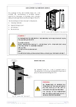
ATTENTION !
923B
The installation and cabling of the battery cabinet must be performed by QUALIFIED
SERVICE PERSONNEL.
924B
Before proceeding to
“Battery cabinet”
connection, follow the
Safety rules
concerning the battery.
925B
Make sure that the UPS is not powered and the
“Battery breaker”
is open (Pos. O).
926B
Before closing the
“Battery breaker”
verify the correct polarity of the battery
connection.
927
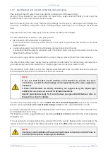
Battery cabinet
928B
Battery
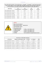
1 battery cabinet / 2 battery cabinets
3 battery cabinets / 4 battery cabinets
931B
Dimensions (W x D x H)
29.80 x 29.50 x 75.00 inches / 757 x 750 x 1905 mm
40.00 x 29.50 x 75.00 inches (1016 x 750 x 1905 mm)
933B
Type of cables connection
934B
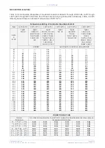
75°C rating; size per NEC Table 310.16 and/or all applicable national and
local codes (see also Section 4.7.4).
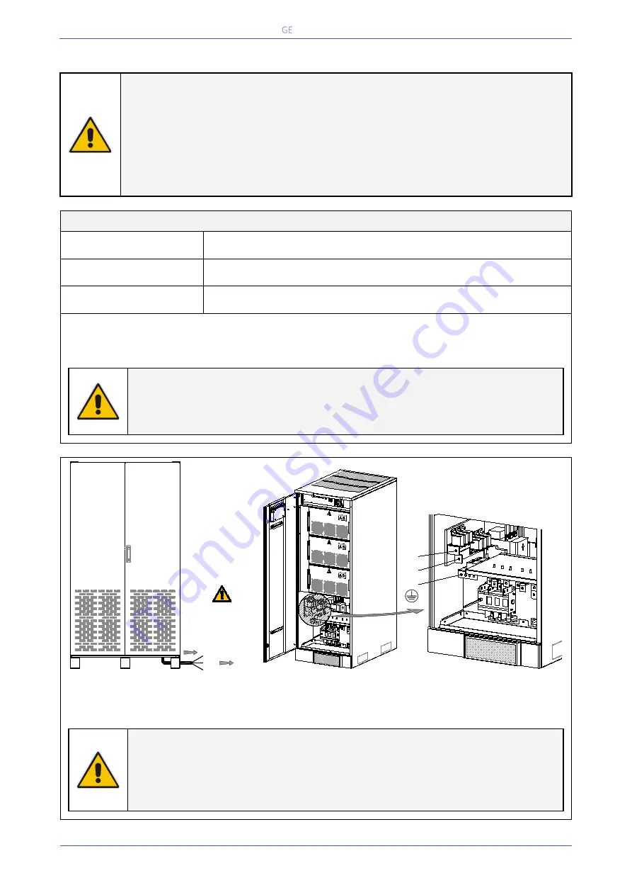
“Battery cabinet”
can be located on either side of the UPS.
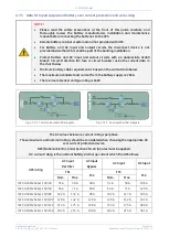
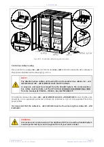
The connecting cables (+/-/PE) are supplied with the battery cabinet.
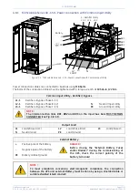
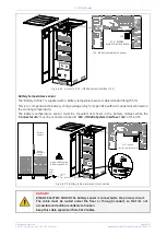
Connect the cables to UPS bus bars “+/-/PE” using M8 bolts with a torque wrench at 195 Lb-in / 22 Nm.
941B
NOTE !
942B
Check for sufficient floor loading capacity.
943B
For further information please consult the
“Installation, Operation &
Maintenance Manual”
of the
“Battery cabinet”
.
1361B
1362B
Fig. 4.8.3-1 Battery cabinet connection to TLE Scalable Series 40 - 150
+ Positive pole
- Negative pole
PE Battery cabinet ground
946B
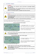
ATTENTION !
947B
It is mandatory to ground the battery cabinet to UPS!
948B
To meet standards concerning electromagnetic compliance, the connection
between the UPS and external
Battery cabinet
must be done by using a shielded
cable or suitable shielded (metal) conduit!
Battery
cabinet
+
EP
O
EP
O
-
+
XA
Q1
TLES
_UL
_040
-150
_S1_
Batt
ery c
abin
et c
onn
ectio
n_01US
Wiring shall comply
to local regulations !
Output
cables
To UPS
bus bars
-
PE (GND)
Q1
_
+
PE

