Critical Power
Modifications reserved
Page 46/146
GE_UPS_OPM_TLE_SCE_M60_M80_1GB_V020.docx
User Manual
TLE Series 600 & 800 CE S1
5.8
ELECTRICAL WIRING
WARNING !
UPS installation and connection must be performed by QUALIFIED SERVICE
PERSONNEL only.
Refer to the “
Safety prescriptions - Installation
” described on
Section 1
.
5.8.1
Mains input connection
NOTE !
Ensure that the AC and DC external isolators are OFF and locked out to prevent their
inadvertent operation.
Do not apply power to the equipment prior to the commissioning by a QUALIFIED
SERVICE ENGINEER.
Before any other input connection, connect and check the earthing wire.
The
Mains input
power connection can be common or separate for
Bypass supply
and
Rectifier input
,
depending on the electrical system provided by the customer.
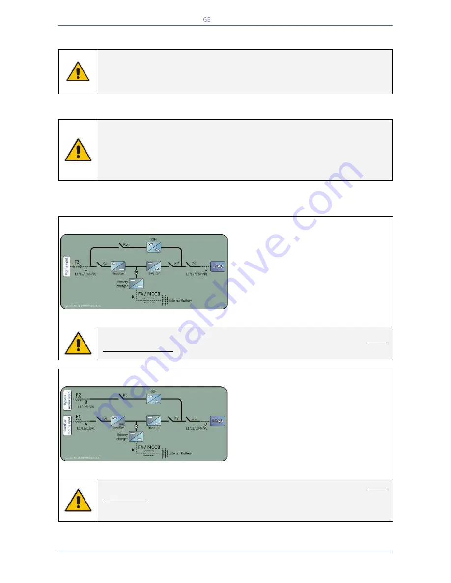
Common mains input Rectifier & Bypass
Fig. 5.8.1-1 Common mains input Rectifier & Bypass
The
same power source
is to be used for both
Bypass supply
and
Rectifier input
(input
F3
)
.
Bear in mind that when the
Mains fuses
are
opened there is a supply failure to the
Rectifier
as well as to the
Automatic Bypass
and
Manual Bypass switch
(only if provided by
customer).
In this case, the interconnection links
BR1
,
BR2
and
BR3
on the input bus bars MUST
REMAIN CONNECTED. See
Fig. 5.9.1-1
and
5.9.3-1
.
Separate mains input Rectifier & Bypass
Fig. 5.8.1-2 Separate mains input Rectifier & Bypass
The
Bypass
and
Rectifier
use different power
sources
(
F1
and
F2
inputs).
In this case, when the
Rectifier-input fuses
are
opened, the
Automatic Bypass
and the
Manual Bypass
(only if provided by customer)
are supplied by the other connection.
In this case, the interconnection links
BR1
,
BR2
and
BR3
on the input bus bars MUST
BE REMOVED. See
Fig. 5.9.2-2
and
5.9.4-2
.
Connect a single input
Neutral
to
Bypass Mains
(inside the UPS, common
Neutral
for
Bypass
and
Rectifier)
.

