Critical Power
Modifications reserved
Page 48/146
GE_UPS_OPM_TLE_SCE_M60_M80_1GB_V020.docx
User Manual
TLE Series 600 & 800 CE S1
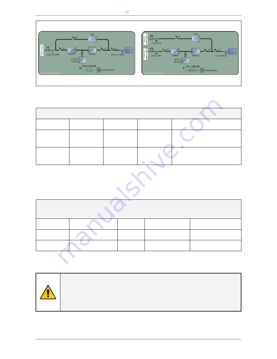
Common mains input Rectifier & Bypass
Separate mains input Rectifier & Bypass
Fig. 5.8.2-1 Common mains input Rectifier & Bypass
Fig. 5.8.2-2 Separate mains input Rectifier & Bypass
Fuses AgL / circuit breakers (3x380/220V, 3x400/230V, 3x415/240V)
UPS model
F1
F2
F3
F4 / MCCB
1
)
TLE Series 600
3 x 1000A
3 x 1000A
3 x 1000A
1600A
2 x FKN36NT100SF / 800A
2
)
TLE Series 800
3 x 1250A
3 x 1250A
3 x 1250A
2000A
2 x FKN36NT125SF / 1000A
2
)
1)
MCCB: can be supplied by
GE
2)
setting value: Ir
–
overload protection. Two parallel battery strings.
Cables section (mm
2
) A, B, C, D, K / IEC 60950-1
Local Standard and cables installation disposal shall be applied
UPS model
A
B
C &D
K
TLE Series 600
3 x (3x185) + 2x150
4 x (3x185)
4 x (3x185) + 2x150
2 x [2x(2x240) + 240]
TLE Series 800
3 x (3x240) + 2x185
4 x (3x240)
4 x (3x240) + 2x185
2 x [2x(4x120) + 2x120]
NOTE !
The delivery and installation of fuses and input/output connections of the UPS are at
the customer’s expense, unless agreed otherwise.
Connect a single input
Neutral
to
Bypass Mains
(inside the UPS, common
Neutral
for
Bypass
and
Rectifier)
.


